I wouldn't try removing that part just yet, Unless the holes are very large around the wires, it may be very difficult to get back in.
Since the leads are so short, it would be very difficult to get it back in if there is something on top of the board to make it stand off more than it does now.
One alternative may be to run wires from the top of the ground terminal to the top of the power stabilizer ground terminal using ring terminals at the blocks.
Yeah if there is space for it, that's what I'll do. The only reason i would want to remove the unknown component is to make sure there's no other damaged traces. It seems its just the ground thats open, but you never know.
But as you stated it its pretty risky removing it and not being able to solder it back on, so it does worry me.
I'll keep the kapton film "trick"in mind that's what I'll have to do just to prevent any short of shorts. Should i be worried about the IC's, would they be likely damaged due to the user mistake?
It's possible that the primary-side ICs were damaged but you can check them when you pull the FETs. Temporarily jump the ground and power up the amp. Does the 494 produce a clean square wave on pins 9 and 10 (assuming that pins 8 and 11 are connected to B+)?
Okay I'll remove the fets and temporary jump the ground terminals. I'll check the wave forms tonight it as soon as i get a chance.
KOk i remove the fets. But i was looking closer at the unknown component and i believe is a transformer and if i do as you (Perry) say then I'll be bypassing it. Don't know if its okay to bypass it or not.
Below is a pic showing the traces below the unknown component. All ground pins had continuity between them as well as the positive.

Below is a pic showing the traces below the unknown component. All ground pins had continuity between them as well as the positive.
I think that they are a group of inductors. If so, bypassing them won't hurt anything, especially not for testing. It's not likely to be a transformer because there is nothing to drive it.
OK. I'll power it up and check the ic's.
Perry this amp uses the sg2525a and right next to it is one label"6n137" its an 8 pin ic.
Perry this amp uses the sg2525a and right next to it is one label"6n137" its an 8 pin ic.
Sorry it took me long, but here are the wave forms i got. Both pins 11 & 14 looked identical.
My scope was set at 2v/div & 20us time/div.
Pin 11
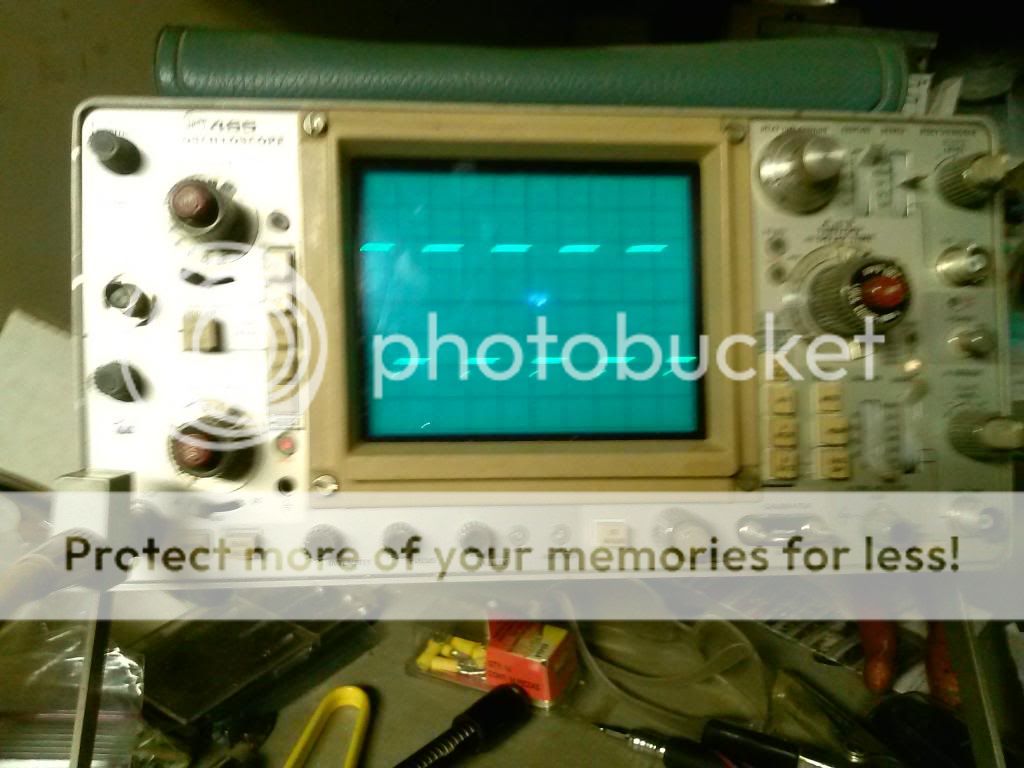
Pin 14
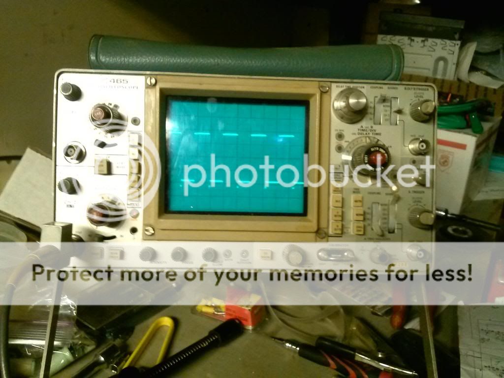
Let me know what else to check for.
My scope was set at 2v/div & 20us time/div.
Pin 11
Pin 14
Let me know what else to check for.
They look OK but in the future, leave your scope set to DC coupling. Read the 'best initial setting' section of page 73 of the web site.
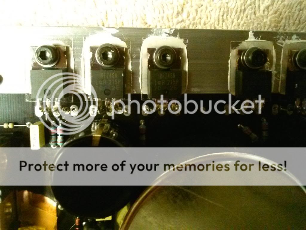
Ok, got the new fets in and gate resistors. I powered it up but notice that the gets (both audio & ps) where getting pretty warm real quick. I don't have mounted to the chassis, so i powered it right off. Will mount it with new compound between the sinks.
Oh i also switch the insulators to mica, because the one if the originals had a small tear and i didn't want to risk it.
Oh i also switch the insulators to mica, because the one if the originals had a small tear and i didn't want to risk it.
Is it possible that there was a fault in the audio section of the amp before they reversed the power connections?
Don't know because once i put it back in the chassis i didn't notice any heat problems. I feed it signal and checked it with my scope.... I only got 16.6vac prior to clipping on each channel. Shouldn't i be getting more like in the 24v area? I didn't have a load on the channels.
I got 1 millivolt dc offset on the channels, when powered on with no load or/and signal. I plan on using some 2 way comps to see if it has any higher voltage or if it gets hot.
I have a 10 amp fuse on the b+ and it didn't blow it.
I got 1 millivolt dc offset on the channels, when powered on with no load or/and signal. I plan on using some 2 way comps to see if it has any higher voltage or if it gets hot.
I have a 10 amp fuse on the b+ and it didn't blow it.
According to the owners manual, its only 50watt x 4 at 4 ohms and 100 x 4 @2 ohms so i guess the voltage i got last night was just right for their power ratings.
Can't wait to listen to it.
Can't wait to listen to it.
Tested and functions properly. Got approx 60 per ch at 4 ohms. Shipped it back to my friend. Thanks Perry and Cecil.
- Status
- Not open for further replies.
- Home
- General Interest
- Car Audio
- Brax X1400 blown fets. Help.