Hi I started a tread with a name that's misleading. So here is the new one:
I'm looking at building a FR speacker based on Fostex FE207E or FX200.
I'm using WinISD for box simulation.
I simulated the recomended BR boxes and I got interesting results. Than I decided to come up with my own BR box.
My question is: How close the simulation graphs are to the real life results and what should I be aming for from the practical stend point.
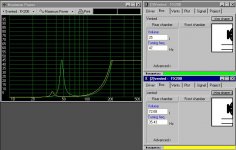
I'm also confused with the Max pwer graph that looks discuraging (mind you this is my first time looking at data like that, so I don't know what to expect).
It looks like (acording to WinISD) The diameter of the port of the recomended enclosure is too small or I'm missing something.
Any suggestions on what to aim for be appreciated.
I don't wan to go for box larger than 75l. But the smaller the better.
Thanks for your help upfront.
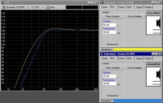
Following are some shots from WinSIM.
Green curve - the recommended enclosure
Yellow - my settings
/Greg
I'm looking at building a FR speacker based on Fostex FE207E or FX200.
I'm using WinISD for box simulation.
I simulated the recomended BR boxes and I got interesting results. Than I decided to come up with my own BR box.
My question is: How close the simulation graphs are to the real life results and what should I be aming for from the practical stend point.
I'm also confused with the Max pwer graph that looks discuraging (mind you this is my first time looking at data like that, so I don't know what to expect).
It looks like (acording to WinISD) The diameter of the port of the recomended enclosure is too small or I'm missing something.
Any suggestions on what to aim for be appreciated.
I don't wan to go for box larger than 75l. But the smaller the better.
Thanks for your help upfront.
Following are some shots from WinSIM.
Green curve - the recommended enclosure
Yellow - my settings
/Greg
Attachments
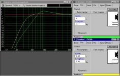
I ran a simulation in my home-brewed program and it gave about the same result. -3dB at ~35 Hz.
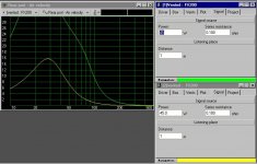
I don't know this software, but the power graph is probably OK. I am not very fond of this type of graph though, it would be far better to show the max SPL as a function of the frequency. Anyway, you are right in that the max allowed power is low for this speaker, and it has to do with a remarkably low Xmax of 1mm, according to http://www.fostex.co.jp/int/pages/sets/prodset.htm .
Max SPL at 50 Hz is actually only 89dB.
The port velocity can be lowered by using a larger port. What dimensions does your port have?
Generally, predictions of the frequency response at low frequencies made by simulation software can be pretty good. It is a completely different thing towards higher frequencies, though. Just don't forget that your room resonances are not simulated... 😉
Svante said:I ran a simulation in my home-brewed program and it gave about the same result. -3dB at ~35 Hz.
I don't know this software, but the power graph is probably OK. I am not very fond of this type of graph though, it would be far better to show the max SPL as a function of the frequency. Anyway, you are right in that the max allowed power is low for this speaker, and it has to do with a remarkably low Xmax of 1mm, according to http://www.fostex.co.jp/int/pages/sets/prodset.htm .
Max SPL at 50 Hz is actually only 89dB.
The port velocity can be lowered by using a larger port. What dimensions does your port have?
Generally, predictions of the frequency response at low frequencies made by simulation software can be pretty good. It is a completely different thing towards higher frequencies, though. Just don't forget that your room resonances are not simulated... 😉
Svante,
Here is the Max SPL graph.
I'll simulate the FX207E and see who is the better candidate, though they recomend the DBR box which I can't simulate.
Thanks for your help.
/Greg
Attachments
GregGC said:
Svante,
Here is the Max SPL graph.
I'll simulate the FX207E and see who is the better candidate, though they recomend the DBR box which I can't simulate.
Thanks for your help.
/Greg
Yes, the SPL curve looks as mine. I cannot find datasheets for FX207E on the web, would you have a link?
That's because I gave you a wrong model #. It's FE207E
Sorry Svante.
What software do you use for simulation?
Is the golden ratio (1:1.618:0.618) very important to follow? The speakers will be too wide and I don't like that.
/Greg
Sorry Svante.
What software do you use for simulation?
Is the golden ratio (1:1.618:0.618) very important to follow? The speakers will be too wide and I don't like that.
/Greg
GregGC said:That's because I gave you a wrong model #. It's FE207E
Sorry Svante.
What software do you use for simulation?
Is the golden ratio (1:1.618:0.618) very important to follow? The speakers will be too wide and I don't like that.
/Greg
I wrote the software myself.
The golden ratio, well, as I understand it that is a way of spreading out the frequencies of the standing waves as much as possible. So in some sense that will optimise the standing wave pattern. But there are other things that need optimising on a speaker. For example the edge diffraction. I am not completely sure about this, but it appears that it is easier to spread out the diffraction effects more evenly if the baffle is high and narrow. For sure, it is unlikely that the golden ratio should be optimum for the baffle size (with respect to diffraction) too.
But this is just me guessing.
The other fostex seems to have a bit low Qts for a BR design. It will drop a bit towards low frequencies. Also this driver too has a pretty small xmax. Do you have a special reason to use fostex drivers?
I want to build a FR single driver speaker with good efficiency. I already have the 2-way that I’m quite happy with (very balanced and solid and airy sound) but I got hooked on sound stage and imaging. I improved it a lot with placement adjustment and the foam strips, but it looks like I can get a lot better results with Single FR speaker (mind you never listen to any of those). I don’t exclude the super tweeter above 10-12khz through a single cap. The type of music I listen is jazz, classical and not much pop, also the TV goes through them. I’m not fan of HT. The existing speakers image and sound better than some of the HT setups anyway. I’m more into “less is more” than just staking speakers. That why I liked the Gainclone and build one (very nice sounding to me).
So I read a lot of good reviews on FE207/FX206/207. FE207 is only $86, so it’s not too bad, the FX200 is around $140. So I decided to give them a try. I don’t have any experience with building cabinets (I’m an Electronics eng.) and it was a very long time when I last read about speaker design. So I’m starting again (this time as a hobby). Decided to go with a simple type of cabinet (ML TL and such woodworking is not of my liking).
By the way the software I use is free and very user friendly and with nice fitters (as much as I can tell). You can give it a try.
http://www.linearteam.dk/default.aspx?pageid=winisdpro
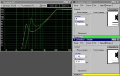
I simulated the FE207E and it looks like a 1-2 Ohm res. In ser. smoothens the graph a lot. Is it a good alternative if it gives me similar results for half of the $.
Thanks again for your time and help.
/Greg
FE207E has 1.5 Ohm res in ser.
So I read a lot of good reviews on FE207/FX206/207. FE207 is only $86, so it’s not too bad, the FX200 is around $140. So I decided to give them a try. I don’t have any experience with building cabinets (I’m an Electronics eng.) and it was a very long time when I last read about speaker design. So I’m starting again (this time as a hobby). Decided to go with a simple type of cabinet (ML TL and such woodworking is not of my liking).
By the way the software I use is free and very user friendly and with nice fitters (as much as I can tell). You can give it a try.
http://www.linearteam.dk/default.aspx?pageid=winisdpro
I simulated the FE207E and it looks like a 1-2 Ohm res. In ser. smoothens the graph a lot. Is it a good alternative if it gives me similar results for half of the $.
Thanks again for your time and help.
/Greg
FE207E has 1.5 Ohm res in ser.
Attachments
Seems OK to me. You should read up on the "baffle step" before you go about building the box. If you are unfamiliar with BS, here is a short intro:The BS leads to a +6dB boost of higher frequencies when the driver is monted in a baffle (or box). This is due to that the speaker radiates only in half space at high frequencies, but in full space at low frequencies. This you may want to compensate for, and also simulate to determine a good placement of the driver on the baffle. A poor baffle design can have a peak between "low" and "high" frequencies of up to 9.5 dB.GregGC said:I want to build a FR single driver speaker with good efficiency. I already have the 2-way that I’m quite happy with (very balanced and solid and airy sound) but I got hooked on sound stage and imaging. I improved it a lot with placement adjustment and the foam strips, but it looks like I can get a lot better results with Single FR speaker (mind you never listen to any of those). I don’t exclude the super tweeter above 10-12khz through a single cap. The type of music I listen is jazz, classical and not much pop, also the TV goes through them. I’m not fan of HT. The existing speakers image and sound better than some of the HT setups anyway. I’m more into “less is more” than just staking speakers. That why I liked the Gainclone and build one (very nice sounding to me).
So I read a lot of good reviews on FE207/FX206/207. FE207 is only $86, so it’s not too bad, the FX200 is around $140. So I decided to give them a try. I don’t have any experience with building cabinets (I’m an Electronics eng.) and it was a very long time when I last read about speaker design. So I’m starting again (this time as a hobby). Decided to go with a simple type of cabinet (ML TL and such woodworking is not of my liking).
You can try my little hack that I used to educate myself about this. It simulates the reflections that occur at the edge of the baffle and appears to be a pretty good predictor of the frequency response effects that diffraction has.
http://www.tolvan.com/diffract.exe
GregGC said:
By the way the software I use is free and very user friendly and with nice fitters (as much as I can tell). You can give it a try.
http://www.linearteam.dk/default.aspx?pageid=winisdpro
I simulated the FE207E and it looks like a 1-2 Ohm res. In ser. smoothens the graph a lot. Is it a good alternative if it gives me similar results for half of the $.
Yes, a series resistance is a classic way of increasing the Qts value, at the cost of efficiency though.
GregGC said:
Thanks again for your time and help.
/Greg
FE207E has 1.5 Ohm res in ser.
Yes, again I get the same result.
JMO but if you are looking for optimum soundstaging and imaging :
Use two small full range drivers e.g. Tangbands in a heavily
faceted cabinet standmounted in free space. Use one driver
for baffle step compensation. Use a sealed box Q ~ 0.6 and
combine with small stereo subwoofers with a linkwitz / riley
12dB octave rolloff.
🙂 sreten.
Use two small full range drivers e.g. Tangbands in a heavily
faceted cabinet standmounted in free space. Use one driver
for baffle step compensation. Use a sealed box Q ~ 0.6 and
combine with small stereo subwoofers with a linkwitz / riley
12dB octave rolloff.
🙂 sreten.
Svante said:
Seems OK to me. You should read up on the "baffle step" before you go about building the box. If you are unfamiliar with BS, here is a short intro:The BS leads to a +6dB boost of higher frequencies when the driver is monted in a baffle (or box). This is due to that the speaker radiates only in half space at high frequencies, but in full space at low frequencies. This you may want to compensate for, and also simulate to determine a good placement of the driver on the baffle. A poor baffle design can have a peak between "low" and "high" frequencies of up to 9.5 dB.
You can try my little hack that I used to educate myself about this. It simulates the reflections that occur at the edge of the baffle and appears to be a pretty good predictor of the frequency response effects that diffraction has.
http://www.tolvan.com/diffract.exe
Yes, a series resistance is a classic way of increasing the Qts value, at the cost of efficiency though.
Yes, again I get the same result.
Svante,
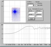
Thanks for your help and the program. It was really interesting to find how much the placement of the speaker on the cab. effects the smoothness of FR. I think now I know why the recommended enclosures and setting of the BR port creates a 4-6dB bump at around 80 Hz. I think it's done to compensate for the "baffle step" loss of LF. I'll keep reading.
In the meantime, I found that I have to use asymmetrical placement (as much as the speaker dimensions allow for) to get the smoothest curve.
That's the best I could come up with:
Attachments
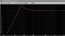
And that's the other one:
So when they are summed the "baffle step" is not as bad.
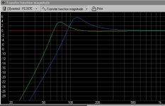
The DBR suggested enclosure is even better (if I simulated properely). I simulated the two volumes separatelly and I assume they have to be added to get the fool curve.
Am I going the right way?
/Greg
So when they are summed the "baffle step" is not as bad.
The DBR suggested enclosure is even better (if I simulated properely). I simulated the two volumes separatelly and I assume they have to be added to get the fool curve.
Am I going the right way?
/Greg
Attachments
sreten said:JMO but if you are looking for optimum soundstaging and imaging :
Use two small full range drivers e.g. Tangbands in a heavily
faceted cabinet standmounted in free space. Use one driver
for baffle step compensation. Use a sealed box Q ~ 0.6 and
combine with small stereo subwoofers with a linkwitz / riley
12dB octave rolloff.
🙂 sreten.
Sreten,
I don't want to waste your time asking you stupid questions. Where can I go and read about what you're suggesting?
Thanks.
/Greg
- Status
- Not open for further replies.
- Home
- Loudspeakers
- Multi-Way
- BR Box design please help.