starting with any reasonable rails filter, reject what's left by 90db ==> dead quiet (unless the layout is screwed up)
Input ripple is only part of the issue, the other one is load-induced ripple.
congratulations!
the only way i know of to post a picture is to use the editor to insert a link to a pic that you have hosted elsewhere, such as google drive or dropbox.
the only way i know of to post a picture is to use the editor to insert a link to a pic that you have hosted elsewhere, such as google drive or dropbox.
The diyAudio gallery is easy to use and the photos stay internal to the forum. Check out the video. 😉
How to use the Gallery Video
How to use the Gallery Video
Attach File
use the "attach" facility built into the posting system.
You find it by clicking on "Go Advanced"
at Attach Files click on "Manage Attachments"
use the "attach" facility built into the posting system.
You find it by clicking on "Go Advanced"
at Attach Files click on "Manage Attachments"
Bild
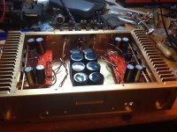
thanks for sharing.
if you don't mind my asking, what do you use to drive it and what do you use for the input cap, if any, that i'm guessing you may have mounted under the board.
No Input cap. My preamp is from Richard Murdey. There are two Black Gate caps at the output. The PSU is the snubber version. The Toroid ist 2x25 V 600 VA. All resistors are TKD from Thel Audio in Germany. The Feedback resistor is direktly soldered from pin 3 to Pin 9 at the LM 3886 with 9 pF Silver Mica cap in parallel.
The 0.18 Ohm are from Isabellahütte 3 Watt manganin.
https://www.hifituning24.de/passive_bauelemente/hochlast_widerstaende/isabellenhuette_pbh/index.php
The 0.18 Ohm are from Isabellahütte 3 Watt manganin.
https://www.hifituning24.de/passive_bauelemente/hochlast_widerstaende/isabellenhuette_pbh/index.php
Last edited:
sure there is drift.
with quality components drift during warmup is extremely low.
here's what i'm getting for each chip's output offset:
cold:
0mv 0mv 1mv / 1mv 0mv 0mv
hot:
1mv 1mv 2mv / 4mv 3mv 2mv
the worst case delta on the first board is 1mv
the worst case delta on the second board is 2mv
the worst case net delta side to side is under 3mv (with one side hot and one side cold).
3mv into either 8R or 4R is less than one milliwatt.
i'm reasonably confident the chip can handle that. 🙂)
Hi,
i have some problems with the ll1545a...
At the picture is a resistor and capacitor...for what...wich value
And i don´t know how to connect the transformer to the PCB...
Maybe someone can help...
My english is very bad sorry
Regards Thomas
i have some problems with the ll1545a...
At the picture is a resistor and capacitor...for what...wich value
And i don´t know how to connect the transformer to the PCB...
Maybe someone can help...
My english is very bad sorry
Regards Thomas
little higher supply voltage
Hi
I am building a clone of this amp. My toroidal is sligthly higher voltage 2x28vac. Will this have any affect on the component values?
Regards Morten
Hi
I am building a clone of this amp. My toroidal is sligthly higher voltage 2x28vac. Will this have any affect on the component values?
Regards Morten
You should check your PSU output voltage when mains is at maximum of the supplier's tolerance.
The 3886 have an absolute limit of 84Vdc, when signal is present.
If one channel is disconnected, then the remaining channel will see a higher supply voltage due to less loading on the PSU.
The 3886 have an absolute limit of 84Vdc, when signal is present.
If one channel is disconnected, then the remaining channel will see a higher supply voltage due to less loading on the PSU.
Z in BPA 300
Hi.. all.
Sorry berofe about my english.
I am very interested in this excellent work.
How about Z input, and how to calculate it?. I am Newbie of this matter. My plan just build BPA300 half, does not build push pull and leave DRV. For my plan build a tube preamp that fits its for maching impedance for this Amplifier. tq.
Build a mono single chipamp first. Learn how that works and what you need to do to get it to work properly.
Then you are ready to build something a bit more adventurous.
Then you are ready to build something a bit more adventurous.
Hello
I am starting with bpa 300 build. I wont be bridging them. Kindly how how to adjust dc for each lm3886 as mentioned in shine7.com.
I am starting with bpa 300 build. I wont be bridging them. Kindly how how to adjust dc for each lm3886 as mentioned in shine7.com.
bpa = Bridged Parallel Amplifier
How can you build a bpa300 if you don't bridge it?
How about adding an extract of the relevant section of shine7?
How can you build a bpa300 if you don't bridge it?
How about adding an extract of the relevant section of shine7?
The PA150 PCB is used in my BPA300 project which uses 2 PA150s in a bridged confirguration. The PA150 PCB can also be used non-bridged to provide 150W output at 2.7ohm load.
The simple answer is that you'll have to put a 4700uF or 10000uF capacitor in series with your speakers. There are other ways of doing it which don't have the LF cutoff dependent on the resistance of the speakers but they aren't catered for here. This is not an especially ambitious implementation of the 3886 and I didn't run mine this way. I'd also say that you are wasting most of what could be done with this by only running it as a PA 150. The advantage of running things differentially is huge. Apart from output impedance, which is again unambitious here with 0R2 resistors balancing the current, there is little to be gained by having 3 LM3886s in parallel except spreading the thermal burden - which is valuable and makes for some of the worst parts of the failings. But a single 3886 can deliver 11A, which is far more than any average speaker can manage.
If you can send the amp a proper differential signal, ie. one the inverse of the other (not that it matters from the point of CMRR) you will find it is a class above what you get from a single ended signal and all the trouble around finding a true ground. When I did that for the first time about 7 years ago, it was the biggest single improvement I had ever heard on any amplifier. It also allows you to drop the gain by half and thus extend the GBWP.
Now if you don't understand this then take Andrew's advice and build a single chip version. I would still advise you to drive it differentially. There is no solution to a non differential amplifier, and it just gets worse the more current you have at your disposal. There is a very good solution otherwise.
- Home
- Amplifiers
- Chip Amps
- BPA300 mono block finished and measured