Ok, now i've got some idea of whats up 🙂 🙁
Kinda dissappointing actually. Basically I need a bigger PS. But first the real story. Ok, so we hooked it up, the only clip leads still attached were input gnd and from the output of the input buffer to the chip inputs. We hooked the whole thing up to the scope, and noise/occillations like crazy. Yikes. So we tested the output of the input buffer, and that looked pretty. Then we tested each parallel side of the amp individually. The - side, then the + side. Both of those looked good. When we hooked them together (bridged), oscillations like crazy. So, what I need to do now, is rip out the clip leads, and solder in real wires, and see if that helps. Ok, now as for the power. Looks like i'm getting (before bridging) about 30 watts out of each parallel side RMS into 8 ohms and close to 50 watts into 4ohms (dang it...could have done this w/ one chip!). Maybe a touch less. The ps voltage just isn't high enough, and it sags 3-4v per rail when the amp is just beginning to clip. So, first I'll solder the input wires, if the oscillations are really robbing of lots of power, then maybe i'll keep the current PS and use it and deal w/it. If I can get rid of the oscillations and the power output is still not adequate, time to get a big toroidal and slap it into my tiny chassis and see what happens more updates to come. later!
-Matthew K. Olson
Kinda dissappointing actually. Basically I need a bigger PS. But first the real story. Ok, so we hooked it up, the only clip leads still attached were input gnd and from the output of the input buffer to the chip inputs. We hooked the whole thing up to the scope, and noise/occillations like crazy. Yikes. So we tested the output of the input buffer, and that looked pretty. Then we tested each parallel side of the amp individually. The - side, then the + side. Both of those looked good. When we hooked them together (bridged), oscillations like crazy. So, what I need to do now, is rip out the clip leads, and solder in real wires, and see if that helps. Ok, now as for the power. Looks like i'm getting (before bridging) about 30 watts out of each parallel side RMS into 8 ohms and close to 50 watts into 4ohms (dang it...could have done this w/ one chip!). Maybe a touch less. The ps voltage just isn't high enough, and it sags 3-4v per rail when the amp is just beginning to clip. So, first I'll solder the input wires, if the oscillations are really robbing of lots of power, then maybe i'll keep the current PS and use it and deal w/it. If I can get rid of the oscillations and the power output is still not adequate, time to get a big toroidal and slap it into my tiny chassis and see what happens
more updates to come. later!-Matthew K. Olson
Ok, soldering in real wires instead of clip leads. There used to be a buzz coming from the tweeters, no more buzz. There is still a hum, but it is minimal 🙂 I may just build up the other monoblock amp as is, because i really don't want to throw any more money at this project...and because there is no room for a nice toroidal in this chassis. Oh well. I already have the other monoblock chassis drilled, so I guess I might as well just use it. Now I know the design works, and if I want to do it right, i'll get pcb's made and make things eaiser on myself. ptp for a gainclone is easy, for 3 parallel chips...what a pain. Its sure is cool looking though ...i'll post listening impressions when i get the 2nd amp done. Later
-Mathtew K. Olson
-Mathtew K. Olson
You need one trafo per channel at around 400VA (National says 380VA), or, better, 500VA.
I would use 2x22 or 2x24V trafos.
And... those MUR860 diodes are good for two chips, you have 8.
Please, use those 35A metal-case bridges there.
If you want to fiddle with serious power, don't think it's cheap.
You need a decent PSU, heatsinks, etc.
The amp will not be small.
Otherwise, use just one chip per channel.
Your trafos and rectification are just perfect for that.
I would use 2x22 or 2x24V trafos.
And...
those MUR860 diodes are good for two chips, you have 8. Please, use those 35A metal-case bridges there.
If you want to fiddle with serious power, don't think it's cheap.
You need a decent PSU, heatsinks, etc.
The amp will not be small.
Otherwise, use just one chip per channel.
Your trafos and rectification are just perfect for that.
Oh yeah, i know 🙂 Next amps will be more powerful. This PS just happened to fit in this case, and so did 6 chips. Way more complicated than it had to be. Oh well. Btw, those diodes don't get as hot as you might think. They were tested. Anyway, thanks for the advice though, although i'm well aware of the need for almost obscene ps's 🙂 i'm usually a fan of excess 🙂
-Matthew K. Olson
-Matthew K. Olson
That sounds valid. Trafo's are probably not uh, sufficient. Oh well. I'll get em next time 🙂
-Matthew K. Olson
-Matthew K. Olson
why not just put 3 lm3886 in paralel insted of 2x3bridge/paralel
I personaly tested both and canot say that I prefer one of them.
My experiece with the mur860`s are not that good(one 3875 pc)
they sounded a little harch and not as open as two MB252 bridges.
Does anyone have simular experience on that?
This is the way the bridges are connected......
http://www.geocities.com/rjm003.geo/rjmaudio/images/diy_gc2a.gif
Well, the 3 in parallel work just fine, you are right about that. The only thing is, the configuration i have my chassis in, it wouldn't be ... convenient. So, i'm finishing the 2nd chassis bpa-200 as we speak. 🙂
-Matthew K. Olson
-Matthew K. Olson
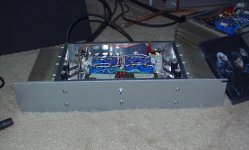
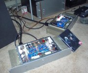
Ok, both bpa-200's w/ 6 chips are working... monoblock style 🙂 I know that the ps's are a little small, but the amps are dang small as well. 2 rack spaces each 🙂 They sound quite nice. Pics to come soon. 🙂
-Matthew K. Olson
-Matthew K. Olson
Ok, you asked for it. If someone wants to host bigger pics let me know, otherwise, this is all i can post ... i take back what i said before, the amps are crazy loud. Quite nice sounding too. My wife was really impressed. I can get them to distort if i do crank em, but i also had both my main speakers plugged into one amp to see how it did w/ a 4 ohm load...handled it quite nicely even when cranked... got a little warmer, but the heatsinks although not optimally positioned, worked fine.
Later!
-Matthew K. Olson
Later!
-Matthew K. Olson
Attachments
looking good there!
how is your dc offset? do you think it could be capable of powering some PA speakers (fairly big ones) quite well?
how is your dc offset? do you think it could be capable of powering some PA speakers (fairly big ones) quite well?
DC offset is about 2mV. Very little offset. Idling heatsink temp is very cool. Sinks get quite warm into 4 ohm load, but they never get hot even when driven hard into an 8 ohm load. If you wanted to drive PA speakers, i'd have a 800-1kva toroidal PER channel 25-0-25 or 30-0-30 would work, although 25-0-25 would be better i think. I'd really like to finalize a pcb for this amp, now i've proven the design works ptp... although it was a lot of work to get these things soldered up. Anyway, good luck w/ it if you do decide to use it 🙂
-Matthew K. Olson
-Matthew K. Olson
Mattyo5 said:
i think the switch is causing the popps... its only a 6A rated switch... i'm using a 3A inrush current limiter though... who knows 🙂
Hey, Matthew. Good to see you're hard at work on another power amp.
Oddly enough, the power switch is stressed more when the amp is turned off. Something about collapsing fields on the transformer, which would not be affected by the inrush limiter.
I learned this tidbit from Hugh Dean in this post on the AudioCircle.
Best regards.
tg3 said:
Oddly enough, the power switch is stressed more when the amp is turned off. Something about collapsing fields on the transformer, which would not be affected by the inrush limiter.
I learned this tidbit from Hugh Dean in this post on the AudioCircle.
Great tip! Hugh also suggests that a bypass (snubber) cap between the switch contacts reduces this problem.
So don't forget to add something like a 10n cap, at least 600v if possible.
Carlos
I have a .22uf cap across AC mains, 250vac... doesn't help any. One amp has it, the other doesn't. Does it need to be closer to the switch? (there is no room for me to get in there)...doh. Higher voltage needed? again doh, just put in an order to digikey... thanks guys
-Matthew K. Olson
-Matthew K. Olson
- Home
- Amplifiers
- Chip Amps
- BPA-200 w/ six chips working w/ pics!