Nope.
According to the data sheet and most any opamp I have seen the null adjustment gets tied to -Vcc through a resistor.
With the null adjustment you should be able to get better than less than 1mv offset depending on the resolution of your meter and the drift factor of the opamp.
You need to test and adjust each stage before connecting them together and then add only one stage at a time as you adjust the added stage until you get them all combined.
jer 🙂
Last edited:
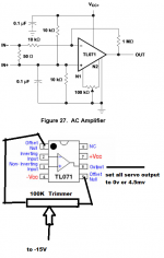
thanks you sir very informative I just wondering because in the page 16 the middle pin of the trimmer is connected to the ground 🙂 sorry for my stupid question 🙂
"You need to test and adjust each stage before connecting them together and then add only one stage at a time as you adjust the added stage until you get them all combined."
after connecting each other, I remove first all the ballast output resistor and retest again.
Thanks again and GOD Bless you
"You need to test and adjust each stage before connecting them together and then add only one stage at a time as you adjust the added stage until you get them all combined."
after connecting each other, I remove first all the ballast output resistor and retest again.
Thanks again and GOD Bless you
Attachments
Last edited:
The reason it is represented as ground in that circuit is because it is being operated from a single ended power supply configuration, else it is still -Vcc.
jer 🙂
jer 🙂
You need to have the Ballast resistors connected when you parallel them.
Also, It makes no difference if it is there or not when you are measuring the offset with no load so just leave them installed even for a single stage at this point.
jer 🙂
Also, It makes no difference if it is there or not when you are measuring the offset with no load so just leave them installed even for a single stage at this point.
jer 🙂
your right sir , thanks you.
now I gathered more data than before, I guess I'm ready to layout it in another pcb.
now I gathered more data than before, I guess I'm ready to layout it in another pcb.
Last edited:
As long as the volume control is coupled to the input of the amplifier through a capacitor (as it should be), then no you don't need it and it has no effect on the Vos or its adjustment.
jer 🙂
jer 🙂
Hi again.
Via my research I found a very interesting topic.
They say instead of using trimmer, the best alternative way is to use coupling capacitor.
My question is, where side I put the coupling resistor?
-To the output of DC- servo or to the output of LM3886? before or after of ballast output resistor?
Via my research I found a very interesting topic.
They say instead of using trimmer, the best alternative way is to use coupling capacitor.
My question is, where side I put the coupling resistor?
-To the output of DC- servo or to the output of LM3886? before or after of ballast output resistor?
Last edited:

I don't know were you read that!!!!?
It is an alternative but IMHO not the best way.
It is okay if you don't mind your signal going through more capacitors than necessary.
And if you don't mind having big bulky caps in your design.
Caps will also limit your low frequency performance as per the value of the output capacitors.
You need a minimum of 4700uf if not greater per chipamp, and it is preferable if they are non polar types, try to find them that big!!.
Have you priced such big cap's lately, all of DCservo circuits cost much much less than that of just one cap by 1/5 if not less.
Not to mention the possibility of having stabilization issues of the many stages trying to work together into a highly reactive load.
It is okay for a single stage running on a single ended supply but it just adds to cost an complexity and can degrade performance for a paralleled configuration.
FWIW
jer 🙂
The whole purpose of having DCservo's in the First place is to eliminate those caps on the output and in the feedback gain loop.
Minimizing the effects of a voltage offset.
There are many amplifier designs out there that can have a much higher Vos issue of a volt or even more, only you don't see it because it is masked by the DC blocking capacitor technique.
I have seen this First hand using my scope while I was monitoring the output of an amplifier and watched the symmetry of a sine wave shift as it changed levels.
Or even seeing the center position of my speakers change and start to push out or even suck in as the signal got louder.
jer 🙂
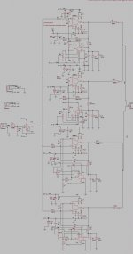
I have a problem of DC servo while I begun and take the first step to build the bpa-200, some of the servo got high voltage output. trimming the dc servo is no-good because the volts change randomly.
video link while I'm testing the single lm3886tf
BPA-200 proving
I put some attachments,
video link while I'm testing the single lm3886tf
BPA-200 proving
I put some attachments,
Attachments
Why don't you keep all of this in the same thread that you started for this project instead of starting a new thread for every little issue.
This would help others to be able to follow along much easier to help you with your project.
I don't have any information at hand as to exactly what is happening but you should be measuring at the output of the LM3886 for an offset voltage.
If there was that much DC voltage at the output of the LM3886 chipamp then your speaker probably would have been fried by now and/or be pushing itself out of its frame!!!
I don't see this happening in the video.
If you are trying to measure just that of the dc servo without the chipamp then the whole circuit would be out of balance and would explain why you are getting the voltages that you are.
FWIW
jer 🙂
Last edited:
thanks for response
I created new thread because the old thread I was created the title is misleading, "PA150 trimmer".
actually sir for my first test I included the chipamp for my first measure, and test the lm3886 output voltage is to high, then I found-out that the output of the dc servo is much higher than the other. in the second measurement I remove the chipamp and the components around the chimpamp to test individually the dc-servo.
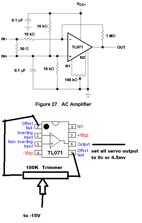
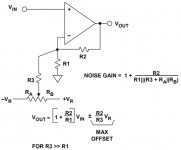
The offset nulling on the TL071 is used to trim the mV offset to zero. You won't be able to trim away 13 V (full rail voltage) of offset. If you have that much offset in your amp, something is not wired right.
I suggest pulling the output resistors (R2, R11, R20, R28) so you can test each part of the circuit separately.
~Tom
I suggest pulling the output resistors (R2, R11, R20, R28) so you can test each part of the circuit separately.
~Tom
Okay.
I have not yet messed with offset trim control inputs on single opamp's.
Most all of the schematics I have seen show the wiper going to -V.
I just found one on the LF356 that shows the wiper going to +V
http://www.ti.com/lit/ds/symlink/lf357.pdf
I have only used the conventional method of feeding the offset voltage directly in to one of the inputs to the opamp as discussed in the other thread and the picture I have posted.
You might try referencing the wiper to ground instead through a resistor of course and see if that works better.
jer 🙂
Attachments
Last edited:
Have a look at the representative circuit schematic in the TL071 datasheet. It shows the bias adjustment points being across the load resistors for the input differential pair. The load resistors go to VEE, hence, the bias pot should go to VEE. If in doubt, one can always pull the adjustment pot and see if the circuit behaves.
~Tom
~Tom
Attachments
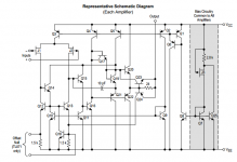
I just noticed the your not feeding the wiper of your offset trimmer through a 1.5k resistor as specified in the data sheet.
I don't have any TL071's else I would be able to check this out myself as well.
jer 🙂
I don't have any TL071's else I would be able to check this out myself as well.
jer 🙂
- Status
- Not open for further replies.
- Home
- Amplifiers
- Chip Amps
- BPA-200 servo problem