Elkaid said:
how can I change the bias ?
If you want the reduced bias current to 30mmA, increase R108 to about 130 ohms
and re-adjust P102 to confirm about 7.5V DC at the gate of the MOSFET.
You could understand more if you read up on the original Pass article.
JH
I lowered R104 to 600 ohms and kept the bias at 40mA for symmetrical clipping. This has the effect of lowering the gain too. I connected resistors of around 50k to 100k at the input, which will form a voltage divider when combined with the 50k input impedance of BOZ. End result? To my tin ears, it sounded wonderful. Try this......
bawang,
I tried both, my way with 30mA and your way with 40mA.
I hope you will try my way too.
JH
I tried both, my way with 30mA and your way with 40mA.
I hope you will try my way too.
JH
Hi JH. I use the BOZ to drive the Leach amp. The Leach amp needs about 2V to drive it to full power. The lowest source output level that I have is my cassette deck with an output of about 400mV. Therefore, I need a maximum gain of 5, which is less than the usual 8 as designed by Nelson. At the same time, I also noticed the unsymmetrical clipping at the higher gain. Nelson also stated that the output will clip at around 15V, with distortion rising at increasing output levels prior to clipping. At a gain of 8 with a CD's output of 2V will theoretically give an output if 16V, way into clipping.
So, I read quite a few posts here on the BOZ and one of the ways suggested was to reduce R104. I did this and it solved both the high gain and unsymmetrical clipping problems. So, I decided to stick with this.... But given the time, I would like to try out your method.... Thanks.🙂
So, I read quite a few posts here on the BOZ and one of the ways suggested was to reduce R104. I did this and it solved both the high gain and unsymmetrical clipping problems. So, I decided to stick with this.... But given the time, I would like to try out your method.... Thanks.🙂
from Taco
I had the same problem, I searched on the forum and I found out that the circuit clips at 1 - 1.5 Volt. And my DAC has an output of near 2 volt, so I bought a 100k pot and found out that the clipping was gone with an extra 100k resistor and replaced the crappy pot with a MF resistor.
Here's another silly question :
Should I put this 100k resistor in serie with the input, in serie with R107 or in parallel with R107 ?
I suppose that I should connect it in serie with R107 is that right ?
Thank you !
Attachments
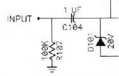
I formed a voltage divider. So the input is halved. So in serie with the input.
Code:
input ---100k--X------C104----
               |
               R107 100k
|Thanks !
Shame on me, it was late I guess... I thought that R107 & C104 were acting as a voltage divider. Now that I've slept a bit, it's clearer
Regards,
Shame on me, it was late I guess... I thought that R107 & C104 were acting as a voltage divider.
Now that I've slept a bit, it's clearer Regards,
Here's some final comments on my Bride of Zen project. I hope that it will be useful to some of you.
I tried all suggestions mentioned in this thread (Thanks guys for your help) and I'm finally using those settings :
bias current @ 28mA (measuring 28VDC through R104 & R204)
Anywhere between 26mA & 30mA was fine.
As suggested, I lowered R104 & R204 (those 3Watts resistors) from 1k ohms to 600 & 820 ohms (again both settings are fine). This lowered slightly the gain but I don't care much.
Adding 22k & 100k resistors in serie with the input was working fine but I removed them since the sound was ok without them. Maybe I'll add them back later if I need them.
The biggest and dumbest error I made is that I was using LINEAR potentiometer instead of Logarithmic. I couldn't turn the potentiometer past 1/50 turn without blowing up my speakers.
I lost a lot of time on this one thinking that my gain was way too high.
By the way I found this thread which covers the same issues as this one
http://www.diyaudio.com/forums/showthread.php?s=&threadid=95&highlight=zen+bride
Elkaid said:
The biggest and dumbest error I made is that I was using LINEAR potentiometer instead of Logarithmic.
You could change the linear potentiometer to the logarithmic by adding just one resistor.
Refer to Pt.1 of http://sound.westhost.com/project01.htm.
JH
Can I drive two power amp with the BOZ......i mean, connect two pair of RCA connector at the outbut of the preamp ???
Looking at the link below there are two parts labeled C105 and C205, respectively. They're sitting right on LIN and RIN.
BOZ Layout Pic
No such parts appear in this site's component list. I gather this is a typo of some sort and that C104 and C204 go there instead?
BOZ article.
Being in the signal path, should these and C103 / C203 be poly film type caps?
Thx for any help...
BOZ Layout Pic
No such parts appear in this site's component list. I gather this is a typo of some sort and that C104 and C204 go there instead?
BOZ article.
Being in the signal path, should these and C103 / C203 be poly film type caps?
Thx for any help...
javven said:Looking at the link below there are two parts labeled C105 and C205, respectively. They're sitting right on LIN and RIN.
BOZ Layout Pic
No such parts appear in this site's component list. I gather this is a typo of some sort and that C104 and C204 go there instead?
BOZ article.
Being in the signal path, should these and C103 / C203 be poly film type caps?
Thx for any help...
Hi
You´re right: C104 and C204
You may use:
Poly film caps: Solen, Audyn Cap, Dayton; $$
Film and foil: Infinicap, Auricap, Hovland $$$$
Paper in oil (PIO) or in beewax: Jensen, Jupiter $$$$$$$
Electrolytic Bipolar: Black Gate N $
It´s a versatile project and I love it.
Check at Passdiy.com>Gallery>Bride of Zen for a lot of pictorial builder´s articles
Enjoy
JC
javven said:Here's the digikey part numbers for my caps.
EF1105-ND
E1106-ND
If is that your question, that´s what I use first
EF1105-ND = C104 and C204, input caps, L/R channels
EF1106-ND = C103 and C203, output caps, L/R channels
Both work fine and you can live with them
JC 🙂
- Status
- Not open for further replies.
- Home
- Amplifiers
- Pass Labs
- BOZ replacement parts