"quoted output of 12wpc is optimistic"
It's more than optimistic.
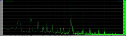
1W 1.8% THD,
3W 4.5% THD.

Yeah all I have seen are spice "measurements"... has anyone actually measured one of these? If it's like the A50, it's probably really bad over 1W of output.
I own the A10, and want to do some of Gianluca's mods (YGG). But after following Stephe on YouTube lately, I think it makes total sense to tame the very high distortion rating before diving into Gianluca's mods. She is modding the A12, but these amps are fairly similar. I looked at the A12's schematics, and there are some differences, but mostly the same. I am wondering whether these mods would change because of these differences? Stephe has a whole series of videos, but the pertinent ones are:
Boyuurange Reisong A12: Initial Modification Results = Win! - YouTube
Boyuurange Reisong A12: Doing the Mods Video #1 - YouTube
Boyuurange Reisong A12: Doing the Mods Video #2 - YouTube
Thank you Stephe!
Boyuurange Reisong A12: Initial Modification Results = Win! - YouTube
Boyuurange Reisong A12: Doing the Mods Video #1 - YouTube
Boyuurange Reisong A12: Doing the Mods Video #2 - YouTube
Thank you Stephe!
I have posted the differences between the two amplifiers. The red highlights on the A10 schematics show differences. There is an unknown value in the far left of the A10, 6N2J schematic, if anybody has opened their amp, or knows the value (see question mark), please let me know.
Attachments
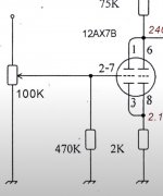
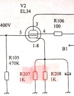
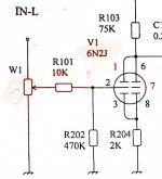
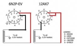
I noticed that the A10's 6N2j schematic doesn't show the highlights well, so the differences are: 1) there is an additional resistor at R101, 2) an unknown resistor value of W1, 3) and the pin layout of the 6N2J (6N2P EV) that varies from the 12AX7 of the A12. Both are dual triode. Here is the pin out schematic.
1) R101 is just a grid stopper, the schematic that came in the box with my A12 shows R101, but it wasn't in the actual amp. 2) I'm sure that W1 is the same 100K pot, 3) Yes you will need to rewire the socket to match a 12AX7, including the heaters. 4) Those two 1K resistors = a 500R one. The amp actually came with a 500R even though the schematic in the box shows two 1K ones.
So yes, an A12 can use these same mods.
So yes, an A12 can use these same mods.
Oh perfect! Thanks Steph! I really enjoyed watching your videos. I could tell your satisfaction from the results of your mods, and this is really what DIY is all about. I have some adapters to make the 6n2j socket work with 12AX7s.I actually like the sound of the 6N2P EVs, and of course will love to roll some 12AX7s. Is there any reason I can't modify this to use the 6n2P EVs (also dual triode), but then use the adapters with 12AX7s? I understand there is a pin difference. Oh,I just realized my picture didn't upload on my previous post about the different pin layouts between these two tubes. I'm a newbie, but might be able to figure out this 6N2J mod, but if you have any words of wisdom, I'll take them. If you feel like I really should stay with the 12AX7 mod only, I'll take your advice. Thanks again!
Attachments
I'm a newbie, but might be able to figure out this 6N2J mod, but if you have any words of wisdom, I'll take them. If you feel like I really should stay with the 12AX7 mod only, I'll take your advice. Thanks again!
Like you said, this is what DIY is all about, give it a try and see how it works out! I have a feeling from the little info I could find, those 6N2J tubes are really close to being electrically like a 12AX7, just a different pinout.
My first post here and have been following Stephe's mod series all along. We need more people like Stephe ... the most underrated YT channel IMHO.
Bofufet: Just to add more info related to your questions. You should have noticed by now the only difference between 12ax7 and 6N2P pin connections is in the heater pins which would be related to Pin 4/5/9. (Pin (123)/(678) are the 2 triode pair pins and not heater related.
You will also noticed in the exact mod Stephe did -> she only modified the 2 Triode pairs pins (123)(678) on the 2 12AX7. She specifically choose NOT to touch any of the heater pins to keep this mod as simple as possible.
Since you already have the 2 socket adapter to convert the A10 (heater wired for 6N2P) to use 12AX7 => By putting in that socket adapter into your A10 you have already done the heater rewiring and now your A10 is actually the same as an A12's in terms of all pin's wiring.
(All the adaptor does is to change the wiring between pin 4/5/9 the same way you would rewire an A10 into an A12 if you do it manually/permanently).
So you can just follow the exact mod she did in her video on your A10. After the mod is done if you plug in 2 12AX7 with adaptors you should get the same results as Stephe did.
The only question/unknown you can find out is after your did the exact mod and you just plug in 2 6N2P (no adaptor) => what will you get??
Firstly I believe it should not damage anything and the modded amp will work just fine using 6N2P (someone more technical should/can confirm this please?) because the characteristics of the 2 types of tube is very close.
The real question is will it sound as good or even better with 6N2P in place?? You can do an A/B test easily since you already have the socket adaptors and able to switch between the 6N2P/12AX7 very easily. Many people would like to know I am sure.
You should also note that Stephe also said she is going to fine tune the A12 a little more (changing value of the 820K plate feedback resistor, etc.) so this is just a starting point of your amp mod/tuning.
Thanks nsfgp! Looks like the mod is easy in Stephe's form. There is an idea proposed about turning the element of one half of the 12ax7 off , like what Stephe did, but take it one step further, and turn the heater off to the off side too. Then disconnect the opposite side of the tube on the opposite side of the amp. Which means in a couple years you just switch the tubes to the other side of the amp and the tubes are virtually new. The idea of cathode poisoning has been brought up, but it looks like that can be taken care of by grounding all the unused pins. I put 3 questions out to any tube DIY aficianados: does one ground that unused heater pin? Is there anything else necessary to avoid cathode poisoning? and can one keep the A10 intact for 6N2's and use 6N2 to 12AX7 adapters ( to use both types of tubes) and still do this heater disconnect mod? Here again is the pin out schematic for both tubes.
Attachments

Last edited:
I put 3 questions out to any tube DIY aficianados: does one ground that unused heater pin? Is there anything else necessary to avoid cathode poisoning? and can one keep the A10 intact for 6N2's and use 6N2 to 12AX7 adapters ( to use both types of tubes) and still do this heater disconnect mod? Here again is the pin out schematic for both tubes.
It doesn't appear the 6N2 has separate heaters per triode, so you can't do the heater disconnect mod with them. It's possible you might be able to modify the adapters to do this? But then you would end up with a left/right adapter etc. And no, do not ground the unused heater.
Honestly, I'm not sure how many years it would take to wear out a 12AX7 in this circuit, these types of preamp/driver tubes last a long time. And unless you have some extra special NOS tubes, a pair of 12AX7 are pretty cheap. It's why I didn't bother. Theoretically it's possibly though.
As Stephe said if you keep the A10 heater wiring (6N2 based) you would need to make 2 custom adaptors for the left and right socket in order to turn off the heater on the unused triode side of the 12AX7.
But making the 2 custom adaptor is not to hard ... best resource I found is with this link/page which you need to follow sort of the REVERSE of what is shown:
SM2YER Goran's Homepage
(The Page showed you how to wire a regular socket adaptor with 12AX7 at the bottom and 6N2 on top which is the reverse of what you have). But it is easy to figure out how to adapt to what you need.
You just need to get 2 regular 9-pin socket-saver. Cut/disconnect 2 pins inside the socket saver and epoxy 2 pins back at the bottom of the adaptor and tie one wire between 2 pins as below. 7 of the 9 pins of the socket-saver will go straight from top to bottom and no need to be cut.
On the channel that you want to use Pin 12349 of the 12AX7 (4/9 HT pins) you tie pin 5 from bottom(6N2) to Pin 9 Top (12AX7); Pin5(Top) and Pin9(bottom) will be floating in the adaptor.
On the channel that you want to use Pin 56789 of the 12AX7 (5/9 HT pins) you tie pin 4 from bottom(6N2) to Pin 9 Top (12AX7); Pin4(Top) and Pin9(bottom) will be floating in the adaptor.
The above modified adaptor will do what you want to disable one side heater for the 12AX7.
Just to throw out some info/idea if you are thinking to do the one side heater disable + swap trick.
That is very simple and cheap: you just need one simple changeover switch: A (COM, Common) is connected to B for UL mode or to C for triode mode.
Just cut the A-B wiring, insert the switch with common in A, and wire C to the other terminal of the switch.
Leave the resistor as it is, so you can have a safe screen grid protection in both the ways.
Switch between A-B and A-C only after powered-off and after having waited for twenty seconds.
It took me much more time to drill the hole in the stainless steel chassis!
What does this mod do for these amps? Is it worth doing? And at what mode does the sound get better?
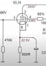
It's only worth trying if you bias the EL34 out of the curvature. See page C3 https://frank.pocnet.net/sheets/129/e/EL34.pdf
In the original setup the EL34 were run at 50mA and 50mA X 500r = 25V cathode voltage (negative grid voltage).
The 290V power transformer gives about 340 volt DC while its current should be limited to 150 - 160mA for cool operation.
If you operate EL34 in triode and swing around 75mA you're in the more linear region. That allows for 25W/0.075A=333V max voltage over the tube. Safer is 90%, so about 300V.
The 3K2:4r/8r output transformers allow a distributed load at 50% of the primary impedance. Originally introduced to get most power from a tube, it showed less distortion could be obtained at the same output power from that pentode. The optimal distribution value varies per tube type.
So, at the expense of some of your precious output power you might win some quality here. Be aware there's a catch up: driving a triode takes more current than driving a pentode in the audio band. Mister Miller is involved so you would probably not get away with the ECC83 or 6N2P. That would ask for another double triode for lowering output impedance, like ECC81, while ending up with a three stage circuit. Not that difficult to design but where's the reward?
I have recently gotten a second hand BRZHIFI A20. It seems almost identical ro the Reisong A10. But the are some minor differences in the way the PCB is utilized. Can anyone help me out what the bypass capacitors on the resistor are for? Also, what are the blocky thinks with 220 on thhem? They look like resistors to me. (I am quite new to all this, although I know how electronics work in general. I built a nixie tube clock once and repaired some broken amps)


I figured out the blue things are the Pilips 200nf 400v capacitors. The bypassed resistors are not stock on the Reisong, but are stock in the BRZHIFI A20.I have recently gotten a second hand BRZHIFI A20. It seems almost identical ro the Reisong A10. But the are some minor differences in the way the PCB is utilized. Can anyone help me out what the bypass capacitors on the resistor are for? Also, what are the blocky thinks with 220 on thhem? They look like resistors to me. (I am quite new to all this, although I know how electronics work in general. I built a nixie tube clock once and repaired some broken amps)
View attachment 1104833 View attachment 1104834
- Home
- Amplifiers
- Tubes / Valves
- Boyuu hifi Equis A10 EL34B+6N2 SE Tube Amplifier with 5Z4P rectifier: review and mod