I might be being overly prissy, but even amongst Non-Polar types there are different types:
Standard 12uF 50V:
Alcap 12.00uF 50V DC Electrolytic Capacitor non-polarised Standard series from Falcon Acoustics, The Leading Supplier of DIY Hifi Components.
Standard 12uF 100V:
Alcap 12.00uF 100V DC High Power Electrolytic Capacitor non-polarised series from Falcon Acoustics, The Leading Supplier of DIY Hifi Components
Low Loss 12uF 100V:
Alcap 12.00uF Low Loss 100VDC Electrolytic Capacitor - Alcap Capacitors Low Loss 50V/100V - Alcap ClarityCap Solen Capacitors
They get bigger with higher rating, and more expensive.
Ok.... Quick question then I'm going to scour the links you sent and order replacements.....
Is it possible to use a polarised cap in place of a Non polarised cap?
I imagine it isn't possible to use a Non polarised cap in place of an circuit that uses a polarised cap?
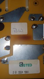
Be interested to know which resistor got hot. Sometimes manufacturers use them as a fuse.
Attachments
A polarised electrolytic is polarity sensitive. In a power supply it must be aligned the right way. It is marked +/- usually. It will blow up if connected wrongly with DC. The voltage chemically destroys the thin oxide layer between the aluminium foil and the electrolyte which is the source of the high capacitance.
A non-polarised is actually two polars connected back to back. It works well enough with an alternating AC signal.
At very low voltage, maybe around +/- 2V you can use a polar capacitor as an AC coupling capacitor. This is done on the output of a lot of CD players because the high value needed is prohibitively expensive with polypropylene or polyester types. The trick is to keep the average voltage on the right side with a tiny transistor voltage offset of maybe 0.5V. But it doesn't sound good, IMO. A lot of high end CD players are identical to cheaper ones except for the addition of a better output capacitor.
But definitely not done in a speaker crossover.
I wouldn't commit myself to what happens to a non-polar with a long term high DC offset voltage applied to it. Just doesn't arise normally. You use a polar in that situation, and it works very well. But the good capacitance must protect the weakened one from DC if I had to guess.
That B&W CM2 Concept 90 seems to be using R2 as part of a LCR impedance correction circuit. 8R2/0.3mH/63uF. I'm not surprised it gets hot.
B&W Group North America Service & Support - Home
Looks like a complicated speaker. There seems to be a CM1 stacked on top of it.. I'm not sure I grasp how it works.
Last edited:
Thanks again for the info Steve.
I'll be posting pics as I progress with the refurb, hopefully it might be of use to others refurbing their Speakers.
I'll be posting pics as I progress with the refurb, hopefully it might be of use to others refurbing their Speakers.
I look forward to it. Before and after pictures always good. Plus one of the splendid overall speaker. 🙂
Sorry if I made that more complicated than it really is. Probably the simple Mundorf 70V will be fine. But the devil is always in the detail. 🙄
I think I am grasping how the Concept 90-TL works. Looks like the CM1 might work standalone with all its protection circuitry and crossover, and the CM2 tower adds some bass with a passive crossover. Bit of a nightmare really though... rather you than me.
I look forward to it. Before and after pictures always good. Plus one of the splendid overall speaker. 🙂
Sorry if I made that more complicated than it really is. Probably the simple Mundorf 70V will be fine. But the devil is always in the detail. 🙄
I think I am grasping how the Concept 90-TL works. Looks like the CM1 might work standalone with all its protection circuitry and crossover, and the CM2 tower adds some bass with a passive crossover. Bit of a nightmare really though... rather you than me.
I'll be leaving the APOC circuitry well alone Steve.... It seems to be fine although some folk bypass/remove it for their own reasons. I'll be replacing the caps and maybe those hot running resistors (I'll stand them of the board a couple of mil), tidying the cabinets and grilles and that will be that. Thinking teak oiled rather than varnish... Job done hopefully.
Quick question Steve.
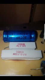
The hot running resistor (8.2ohm, 11w)...can I replace that safely with a higher rated resistor and would it run cooler?
Thanks for your help... Again.
The hot running resistor (8.2ohm, 11w)...can I replace that safely with a higher rated resistor and would it run cooler?
Thanks for your help... Again.
Last edited:
That resistor conceivably got hot through some fault condition, like running the CM2 without the CM1 connected. I'd have to model the whole thing to be sure:
Software | Visaton
Not hard to use similar drivers to see how it works electrically.
But really, simple troubleshooting ought to reveal if there is a serious problem. Coils and resistors are tough as old boots, and can be unsoldered to check the other components in series. Being 0.3mH / 8R2@11W / 63uF here.
That's not the worst scorching I've ever seen. Not much can go wrong with a simple bit of coiled copper resistance wire IMO. Either works or it doesn't. But nothing stopping you replacing it at all.
Last edited:
That resistor conceivably got hot through some fault condition, like running the CM2 without the CM1 connected.
I think I know what that might be.
When I picked them up from the chap in Erith, he'd had the polarity of the cm1s out of phase +on- and - on+..... Now that was on the cm1 but the hot resistor is on the cm2 board, however they do link up so maybe thats what caused it? The polarities were correct on the second set of speakers.
Polypropylene caps.....apart from size and expense are there any other negative points using them to replace electrolytic caps? I dont plan on using them to replace the complete range of electrolytics, just the ones i'm struggling to get hold of.
Thanks.
Thanks.
I cant get my head around this. My old capacitor is 75uf, 50vdc, diameter 25mm, circumference 78.5mm and length 34mm....the replacement Vishay is tiny by comparison.....is this definately ok to use to replace the big, old Pye cap? Sorry to be a pain but i don't want to screw this up.😀
Product Information Vishay Cap:
Capacitance: 75µF
Voltage Rating: 50V
Product Range: ATOM TVA Series
Capacitance Tolerance: -
Capacitor Terminals: Axial Leaded
Diameter: 9.525mm
Lead Spacing: -
Height: 20.625mm
Operating Temperature Min: -40°C
Operating Temperature Max: 85°C
Lifetime @ Temperature: -
ESR: -
Vishay Atom TVA series is a polar capacitor. Not what you want at all.
I can't imagine why some values are hard to get. Falcon seem to have loads in preferred values like 33uF, and selected values like 30uF. You follow?
Talking about the Concept 90-TM bass module, it seems to be prone to overheating crossover, maybe with party use:
B&W Concept 90 Crossover advice requested
Probably a ventilation problem.
Vishay Atom TVA series is a polar capacitor. Not what you want at all.
I can't imagine why some values are hard to get. Falcon seem to have loads in preferred values like 33uF, and selected values like 30uF. You follow?
Talking about the Concept 90-TM bass module, it seems to be prone to overheating crossover, maybe with party use:
B&W Concept 90 Crossover advice requested
Probably a ventilation problem.
See...i told you i was new to all this. 😀
Its more the size differences that were of concern but if thats just down to modern caps being more efficient then i'll go with it. I'll make sure i get the right polarity......now.
😉Here we go:
We don't know the voltage or loss ratings here.
75uF is a preferred value, so ought to be easy.
30uF is unusual. I don't know if Falcon have it. 33uF wouldn't be the end of the world.
20uF is another odd one. 22uF will definitely do.
80uF is an odd one. 75uf or 82uF should be OK. Get 75uF if you use 22uF. 82uF if you get 20uF.
8uF is an odd one, but I have some. in MKP. But 8.2uF will work.
15uF is a preferred value again.
If you can't get the same voltage (50 or 100V), go higher. And get low-loss if you can afford it.
ClarityCap Solen & Alcap capacitors, audio components for loudspeaker crossovers.
EW, it's trickier than I thought! 😱
Couldn't find 75uF, so 80uF will have to do. But I've found everything else exact except 15uF. I'm sure 16uF will do:
Two here:
Alcap 50V & 100V Low Loss Electrolytic capacitors for all audio and hi-fi loudspeaker crossover applications
Couldn't find 75uF, so 80uF will have to do. But I've found everything else exact except 15uF. I'm sure 16uF will do:
Two here:
Alcap 50V & 100V Low Loss Electrolytic capacitors for all audio and hi-fi loudspeaker crossover applications
Here we go:
We don't know the voltage or loss ratings here.
75uF is a preferred value, so ought to be easy.
30uF is unusual. I don't know if Falcon have it. 33uF wouldn't be the end of the world.
20uF is another odd one. 22uF will definitely do.
80uF is an odd one. 75uf or 82uF should be OK. Get 75uF if you use 22uF. 82uF if you get 20uF.
8uF is an odd one, but I have some. in MKP. But 8.2uF will work.
15uF is a preferred value again.
If you can't get the same voltage (50 or 100V), go higher. And get low-loss if you can afford it.
ClarityCap Solen & Alcap capacitors, audio components for loudspeaker crossovers.
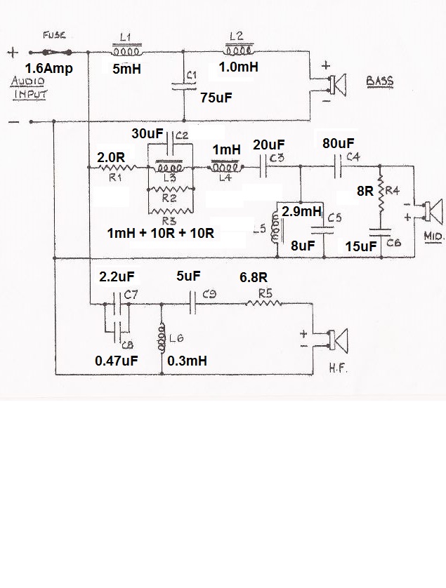
Thats fantastic Steve, still searching but definately getting somewhere. Thanks for the schematic, thats going to come in handy.
I drew up that schematic years ago. Got fed up with looking at component numbers and keep having to refer to a list at B&W! 😀
I had a look Wilmslow too:
https://www.wilmslowaudio.co.uk/mundorf-electrolytic-ecap-capacitors-130-c.asp
That looks doable. 10% is usually good enough.
With typical Teutonic Efficiency, Mundorf build to preferred values. No British Pole, Rods and Perches and Chains and Bushels... 😎
I had a look Wilmslow too:
https://www.wilmslowaudio.co.uk/mundorf-electrolytic-ecap-capacitors-130-c.asp
That looks doable. 10% is usually good enough.
With typical Teutonic Efficiency, Mundorf build to preferred values. No British Pole, Rods and Perches and Chains and Bushels... 😎
These are the very capacitors I recommended back in post #4.I had a look Wilmslow too:
Mundorf Electrolytic ECap Capacitors
Hey-ho!

I think the closest i can get to 75uf is using these two in parallel?
68 fd ECap100 Electrolytic Capacitor
6 8 fd ECap70 Electrolytic Capacitor
68 fd ECap100 Electrolytic Capacitor
6 8 fd ECap70 Electrolytic Capacitor
These are the very capacitors I recommended back in post #4.
Hey-ho!
Thats the ones i'm looking at now....i've got 6 boards worth of caps to sieve through. 😀
- Home
- Loudspeakers
- Multi-Way
- Bowers & Wilkins DM2 Series ii Rebuild