Hey people,
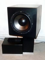
no excuses, don't know how I managed to do this, but I connected the 12V line to the amp with reversed polarity (yes, it's even printed on the pcb not to do this). While waiting for a suitable smps, I tried the amp with my bench psu which could deliver 50V, but only around 100VA, and everything went fine. As the smps arrived, I made everything fitting in the case underneath the sub, and installed two 120mm fans for an appropriate airflow, also. This was quite some work to do, including many hours of painting-sanding-painting-sanding-pain... .
Whatever, I switched it on, and the 12V wire went up in smoke. As hope dies last, and the two green led's were still lighting, I connected everything correctly and gave it a 2nd try. I switched it off as soon as the small blue spark showed at "D2".
Ok, it's dead. But I don't want to bury it, if there is a maybe a chance to fix it. The problem, I'm not the worst with the soldering iron, but I'm just a mechanic.
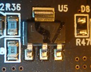
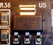
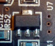
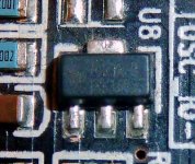
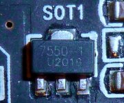
The green lights still light when 12V are attached, and just by looking at it, I do not see burned or "exploded" parts. Just U5, a LM317G voltage regulator looks a little strange.
What could I Do, what could I try, to maybe save this amp?
I've got no oscilloscope, just a multimeter.
best regards
Jochen
no excuses, don't know how I managed to do this, but I connected the 12V line to the amp with reversed polarity (yes, it's even printed on the pcb not to do this). While waiting for a suitable smps, I tried the amp with my bench psu which could deliver 50V, but only around 100VA, and everything went fine. As the smps arrived, I made everything fitting in the case underneath the sub, and installed two 120mm fans for an appropriate airflow, also. This was quite some work to do, including many hours of painting-sanding-painting-sanding-pain... .
Whatever, I switched it on, and the 12V wire went up in smoke. As hope dies last, and the two green led's were still lighting, I connected everything correctly and gave it a 2nd try. I switched it off as soon as the small blue spark showed at "D2".
Ok, it's dead. But I don't want to bury it, if there is a maybe a chance to fix it. The problem, I'm not the worst with the soldering iron, but I'm just a mechanic.
The green lights still light when 12V are attached, and just by looking at it, I do not see burned or "exploded" parts. Just U5, a LM317G voltage regulator looks a little strange.
What could I Do, what could I try, to maybe save this amp?
I've got no oscilloscope, just a multimeter.
best regards
Jochen
Attachments


How many Watt do you expect from such a module, driven by 12 V? Is 18W/4Ohm enough? Thats all you can expect, even from a bridged amp. These amps only reach their advertised power with 10% distortion and the maximum voltage applied. Such an 48 Volt amp only delivers a fraction of the promised power if driven by 12V. Think of it as a 4 cylinder engine with 3 spark plugs missing.
If you want to drive a sub from 12V in a car, get a good car amp made for 12V from eBay. Such an amp has an internal voltage converter and can deliver enough power. I constandly see great car amps offered for sub 50€, as todays kids are unable to install anything in a car.
Do not expect any amp to be immune to reversed polarity.
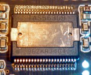
Your burned amp is done, it has no prtection diode. Parts and labour are a multiple of it's retail price. If your wire to the battery smoked, the same has happened inside the main amplifier chip. The power did not go no where...
If you want to drive a sub from 12V in a car, get a good car amp made for 12V from eBay. Such an amp has an internal voltage converter and can deliver enough power. I constandly see great car amps offered for sub 50€, as todays kids are unable to install anything in a car.
Do not expect any amp to be immune to reversed polarity.
Your burned amp is done, it has no prtection diode. Parts and labour are a multiple of it's retail price. If your wire to the battery smoked, the same has happened inside the main amplifier chip. The power did not go no where...
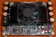
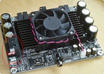
Just take a look at the picture. The TAS5630 needs two voltages: 12V for control and up to 50V (single) for power. I'm using a 12V/1A wallwart & a 48V/10A smps.How many Watt do you expect from such a module, driven by 12 V? Is 18W/4Ohm enough? Thats all you can expect, even from a bridged amp. These amps only reach their advertised power with 10% distortion and the maximum voltage applied. Such an 48 Volt amp only delivers a fraction of the promised power if driven by 12V. Think of it as a 4 cylinder engine with 3 spark plugs missing.
If you want to drive a sub from 12V in a car, get a good car amp made for 12V from eBay. Such an amp has an internal voltage converter and can deliver enough power. I constandly see great car amps offered for sub 50€, as todays kids are unable to install anything in a car.
Do not expect any amp to be immune to reversed polarity.
Your burned amp is done, it has no prtection diode. Parts and labour are a multiple of it's retail price. If your wire to the battery smoked, the same has happened inside the main amplifier chip. The power did not go no where...
best regards
Jochen
Attachments
Last edited:
Thank you for the tipp. I will check it & report.Hi first measure the LM317.
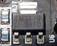
Ok, I did not desolder the voltage regulators. What I can say is, none of the 5 voltage regulators I found has a short between any pin. With 12V attached I measure 5V at the 5V-connectors lined up at the sides of SW1.
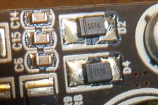
I checked resistance of D2/D4 and D10/D12 anode > kathode and vice versa with the same results at all four. As far as I understood the net-description, they should be ok (as for I saw a little blue spark at D2 as I attached 48V).
Question: may I attach 12V without the heatsink attached to the chip (or could I mount a small substitute HS to measure Voltages at the parts normally covered by the HS)?
Attachments

It is most likely to affect electrolytic caps and semiconductors with polarity reversal.
Whip out power IC as that will be toast.
Check all electrolytics for shorts and replace as required.
Then test all semiconductors and replace as required.
Whip out power IC as that will be toast.
Check all electrolytics for shorts and replace as required.
Then test all semiconductors and replace as required.
- Home
- Amplifiers
- Class D
- Bought a TAS5630 and instantly killed it - Chance for repair?