Hi all
This amp doest not power on.Safe light on the front is on . Amp has no rail voltage.
Ther is no voltage on the gates of the power supply FETs.I am getting 13.02v on only
One pin of the PWM ic (will comfirm which pin later).All fuse test ok.Any pointers for this
Amp?
This amp doest not power on.Safe light on the front is on . Amp has no rail voltage.
Ther is no voltage on the gates of the power supply FETs.I am getting 13.02v on only
One pin of the PWM ic (will comfirm which pin later).All fuse test ok.Any pointers for this
Amp?
If you apply both remote and B+ at the same time, the amp probably won't power up. Connect B+ and ground, then apply remote voltage.
I tried that but no luck.I think pin 15 should have the same voltage with pin 13
But I still can not find out why voltage is not reaching that pin.I read on the dvd these
two pins are connected sometimes but on this amp they are not connected together
Sg3525
1: .00
2: .00
3: .00
4: .00
5: .00
6: .00
7: .02
8: .13
9: .21
10: .00
11: .00
12: .00
13: 15.71
14: .00
15: .11
16: .00
Lm339D
1: .27
2: .73
3: .86
4: .04
5: .00
6: 13.28
7: .86
8: .73
9:.27
10: 15.55
11: .24
12: .73
13: 6.27
14: .84
Last edited:
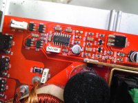

There should be a transistor near the LM339 that has it's collector directly connected to pin 15 of the SG3525. Find it and post the voltage on all 3 pins.
Q77 mark 4G
Pin:1 15.44
Pin:2 15.47
Pin:3 .04
Q76 also has one leg connected to pin 15
Pin:1 .04
Pin:2 .04
Pin:3 .24
Pin:1 15.44
Pin:2 15.47
Pin:3 .04
Q76 also has one leg connected to pin 15
Pin:1 .04
Pin:2 .04
Pin:3 .24
Post the pins on the 339 that are connected to the bases of those transistors (possibly through resistors).
The base of Q76 is connected to pin 10 through 1500 and 90 ohm resistor. The base of Q77 is not connected to
the 339.I have 339 ic in stock should I replace it?
Any one have the schematic for this amp?
the 339.I have 339 ic in stock should I replace it?
Any one have the schematic for this amp?
Is there a 4.7 ohm SMD resistor with one end connected to the B+ terminals and the other end connected to pin 3 of the 339?
It's likely to be relatively large. Is it within tolerance?
It's likely to be relatively large. Is it within tolerance?
Ok sorry about that. I number the pins on the 339 wrong.The resistor test good and the base of Q76 is connected to
Pin 3 of the 339 through 1500 and 90 ohm resistor.
339
Pin1: .73
Pin2: .27
Pin3: .15.55
Pin4: .24
Pin5: .73
Pin6: 6.27
Pin7: .84
Pin8: .27
Pin9: .73
Pin10: .86
Pin11: .04
Pin12: .00
Pin:13.28
Pin14: .86
Pin 3 of the 339 through 1500 and 90 ohm resistor.
339
Pin1: .73
Pin2: .27
Pin3: .15.55
Pin4: .24
Pin5: .73
Pin6: 6.27
Pin7: .84
Pin8: .27
Pin9: .73
Pin10: .86
Pin11: .04
Pin12: .00
Pin:13.28
Pin14: .86
Last edited:
There should be a transistor connected to the base of Q77 (possibly through a resistor and the power LED). The emitter will be connected to a zener diode. What is the circuit board designation for that transistor and what is the DC voltage on all 3 legs.
If it's a BC850, you're correct. I'm accustomed to seeing 2G transistors in Rockford amps and they're PNP.
If it's an NPN, it doesn't appear that you have remote voltage reaching it. Follow the trace from the remote input through the various components to the base of this transistor. Where do you lose 12v?
If it's an NPN, it doesn't appear that you have remote voltage reaching it. Follow the trace from the remote input through the various components to the base of this transistor. Where do you lose 12v?
Both the base and emmiter are connected to the the remote through a 5.6k resistor.
Remote voltage 15.55 is reaching both resistors.
Remote voltage 15.55 is reaching both resistors.
What is the circuit board designation for the resistor connected between the remote and the base of the transistor?
- Status
- Not open for further replies.
- Home
- General Interest
- Car Audio
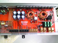
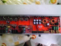
- Boston GT 50