Hello all,
So, I had a working Boss BF-1 and my bandmate had accidentally plugged 18V into it for about 5min until I realized something sounded off.
Now, when the pedal is disengaged/bypassed (but not true bypass) it has a loud noise that runs through the signal. Yet, when engaged it seems to be working okay. The same noise is there, but it is buried underneath the effect.
I tried emailing Roland to get a schematic to help me trouble shoot potential problems. They denied me and referred me to their certified repair places. I called a couple of them trying to see if they could share the schematic, with no luck.
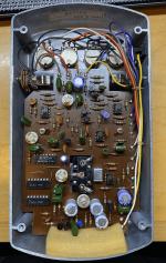
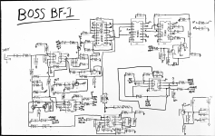
So, I went to work reverse engineering the PCB (photo attached). Since it was only one layer of traces, it wasn't too bad to draw it out. I first drew it out on a white board (photo attached) and then made a better looking schematic on KiCad (pdf attached).
I am mostly creating this thread to share the schematic for others since I was unable to find one online. But I want to be clear that there could be error in this. I am not saying this is 100% the Boss BF-1 schematic.
I made sure to look up all the datasheets (all attached) of the active components and tried to decipher some of the ceramic capacitor markings the best I could.
There is room for error in this schematic, but I really did try my best.
I also created this thread to get some help because I would rather not go and replace all these components if I do not have to.
So, here is what I have found so far and where I am:
Alright, thats all I got! If anyone has any idea on what to look for or see's any potential problem, please let me know!
So, I had a working Boss BF-1 and my bandmate had accidentally plugged 18V into it for about 5min until I realized something sounded off.
Now, when the pedal is disengaged/bypassed (but not true bypass) it has a loud noise that runs through the signal. Yet, when engaged it seems to be working okay. The same noise is there, but it is buried underneath the effect.
I tried emailing Roland to get a schematic to help me trouble shoot potential problems. They denied me and referred me to their certified repair places. I called a couple of them trying to see if they could share the schematic, with no luck.
So, I went to work reverse engineering the PCB (photo attached). Since it was only one layer of traces, it wasn't too bad to draw it out. I first drew it out on a white board (photo attached) and then made a better looking schematic on KiCad (pdf attached).
I am mostly creating this thread to share the schematic for others since I was unable to find one online. But I want to be clear that there could be error in this. I am not saying this is 100% the Boss BF-1 schematic.
I made sure to look up all the datasheets (all attached) of the active components and tried to decipher some of the ceramic capacitor markings the best I could.
There is room for error in this schematic, but I really did try my best.
I also created this thread to get some help because I would rather not go and replace all these components if I do not have to.
So, here is what I have found so far and where I am:
- I noticed the electrolytic caps where max voltage rating of 16V. I took em out, tested them all and replaced all but a few (C10 & C21, they were good). I replaced the others with Nichicon caps that matched the previous caps almost exactly (capacitance, rated voltage, temp rating, and diameter). This did not fix the noise, but it did make the effect sound much more lush and full which is nice.
- I have looked through all the datasheets and, to me, it seems like all the active components can handle 18V, yet I do not know about the signal strength increase due to 18V that could have maybe broken a component. The only active components that could have hit the hardest is the Reticon SAD1024 since the datasheet states the absolute max voltage it can take is 18V. But that chip is used in the effect line for delays and the effect sounds just fine. So, I'm at a loss there.
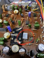
- The Zener diode (D6) is fine. I have yet to take out the other diode to see what they are and if they work.
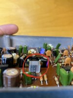
- C33 is a puzzle to me. It is also the (?) on the whiteboard schematic. I have attached a picture of it. Im not completely sure what it is, but it does say 1uF on it. If anyone has any clue, please let me know. I have tried to find it online to identify what it is exactly.
Alright, thats all I got! If anyone has any idea on what to look for or see's any potential problem, please let me know!
Attachments
-
 IMG_5390.png1.4 MB · Views: 878
 -
 IMG_5453.png806.2 KB · Views: 672
 -
Boss BF-1.pdf163.1 KB · Views: 174
-
4558D-JRC.pdf121 KB · Views: 104
-
SAD1024_Reticon.pdf786.7 KB · Views: 114
-
TC4011 datasheet.pdf404 KB · Views: 614
-
TC4013 datasheet.pdf343.8 KB · Views: 144
-
C900 datasheet - NEC - Samsung.pdf494.4 KB · Views: 756
-
K30A datasheet.pdf152 KB · Views: 91
-
D571_NEC.pdf186.6 KB · Views: 121
-
 IMG_5480.jpg274.2 KB · Views: 411
 -
 IMG_5481.jpg450.5 KB · Views: 472
If you mean 18VDC was plugged into the input jack, that might have been ok since there is a blocking capacitor.
But if the (-) capacitor terminal is connected to the input jack, which is likely because of the single supply circuitry,
then the capacitor would have been reverse biased and probably damaged. If it were shorted, then the 18V would
have been applied to the circuit directly and caused damage at various places, maybe the ICs, transistors, etc.
If the 18V supply had its (-) terminal connected to the positive jack terminal, the damage could be worse
and the capacitor would be much more over-voltage.
Last edited: