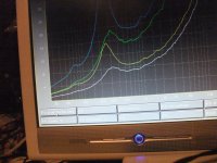
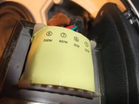
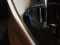
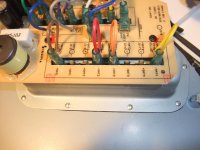
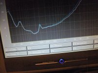
BOSE Model 32 - various Plots for Impedance and SPL
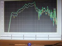
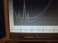
Connections for impedance plots in first and SPL plots in second image:
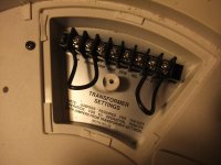
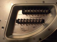
White: "C" and "+ in"
Blue: "C" and "2"
Green: "C" and "4"
Yellow: (only SPL-plot) pos. pol on "16", "C" on "2"
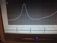
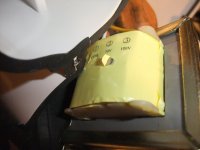
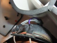
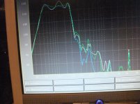
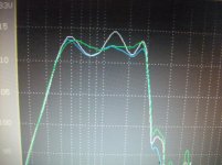
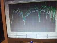
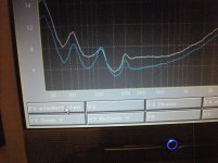
Connections for impedance plots (third image) and sound pressure level (near field) in fourth image (neg. pol = GND):
White: pos. pol on "8", "C" on "2"
Yellow: pos. pol on "16", "C" on "2"
Green: pos. pol on "16", "C" on "4"
Blue : pos. pol on "32", "C" on "4"
Last image show, that is no difference both between connections on driver and connections on auto transformer "- in" and "C" with connected driver. This means, the windings in series to the driver in my schematic must be replace by wires without inductivity.
Connections for impedance plots in first and SPL plots in second image:
White: "C" and "+ in"
Blue: "C" and "2"
Green: "C" and "4"
Yellow: (only SPL-plot) pos. pol on "16", "C" on "2"
Connections for impedance plots (third image) and sound pressure level (near field) in fourth image (neg. pol = GND):
White: pos. pol on "8", "C" on "2"
Yellow: pos. pol on "16", "C" on "2"
Green: pos. pol on "16", "C" on "4"
Blue : pos. pol on "32", "C" on "4"
Last image show, that is no difference both between connections on driver and connections on auto transformer "- in" and "C" with connected driver. This means, the windings in series to the driver in my schematic must be replace by wires without inductivity.
Attachments


Last edited:
In a nutshell, yes.This means, the windings in series to the driver in my schematic must be replace by wires without inductivity.
Agree that sometimes terminal strips or connectors may be wired in a confusing way.
DCR measurements do not help much at such low values.
Thanks for reporting back!Connections for impedance plots (third image) and sound pressure level (near field) in fourth image (neg. pol = GND):
White: pos. pol on "8", "C" on "2"
Yellow: pos. pol on "16", "C" on "2"
Green: pos. pol on "16", "C" on "4"
Blue : pos. pol on "32", "C" on "4"
Just to be clear - are you measuring impedance between pin "-in" and pin "8", while pin "C" is connected to pin "2" (white on third image)?
Also, are you measuring impedance between pin "-in" and pin "16", while pin "C" is connected to pin "2" (yellow on third image)?
If so, then you succeed to have safe 8-ohm nominal impedance for connecting to a regular amplifier.
But, what is bothering me is a somewhat low impedance below 150 Hz. Please try my suggestion from post #14: measure impedance between pin "-in" and pin "4", while pin "C" is connected to pin "1". Also, measure impedance between pin "-in" and pin "8", while pin "C" is connected to pin "1". Compare those measurements with the third image (white and yellow plots).
Yes, as I wrote in my post #16:Last image show, that is no difference both between connections on driver and connections on auto transformer "- in" and "C" with connected driver. This means, the windings in series to the driver in my schematic must be replace by wires without inductivity.
1)... the only mistake I see is that the "windings" left and right from the driver (next to "white" and "black" wires) do not exists in reality - they are simply connecting wires. All auto-transformer windings are between Input pins "-" and "+"
Exactlly.Thanks for reporting back!
Just to be clear - are you measuring impedance between pin "-in" and pin "8", while pin "C" is connected to pin "2" (white on third image)?
Also, are you measuring impedance between pin "-in" and pin "16", while pin "C" is connected to pin "2" (yellow on third image)?
If so, then you succeed to have safe 8-ohm nominal impedance for connecting to a regular amplifier.
But, what is bothering me is a somewhat low impedance below 150 Hz.
The impedance below 150Hz was determined by the very low DCR of voice coil - go also to the datasheet for Bose 901 replacement driver under
GRS RSB901-1 Tieftoner kaufen - SoundImports
The driver unit in this satellite speaker "Model 32" is basically the same.
In the moment is for me the main question, how looks the schematic of the integrated passive high pass filter in the associated subwoofer unit of this Freespace system and the consequences regarding the resulting individual plots of frequency response from the whole sub sat system.
According the operating manual there are to connect single sat and two sat speakers in series.
Together with the various connection possibilities at the sat speaker itself (from my previous post) there are many combinations for try.
The influence of the whole high pass character is great - so I think.
Next days my friend brings me this subwoofer for dismantling and checking schematic impedance and frequency response plots.
I will report again after checking this.
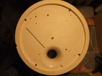
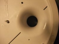
Image No 6 from post #2 shows the version of "Model 32" with 4 ohms. Who can post the images from inside parts and rear side (connection terminal) of this version ?
Actually I want to know, if there is the same low DCR driver with auto transformer in use or a driver with 3R2 voice coil DC resistance.
Last edited:
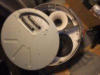
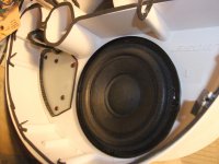
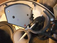
Strip Down of Bose® FreeSpace®3 Ser. II Subwoofer
Here the image series:
Here the image series:
Attachments
-
 Bose® FreeSpace®3 Ser. II Front with cover.jpg1,010.7 KB · Views: 86
 -
 Bose® FreeSpace®3 Ser. II Front-I.jpg675 KB · Views: 67
 -
 Bose® FreeSpace®3 Ser. II Front-II.jpg755.5 KB · Views: 63
 -
 Bose® FreeSpace®3 Ser. II Sticker.jpg990.1 KB · Views: 83
 -
 Bose® FreeSpace®3 Ser. II Terminal Transf.jpg842.3 KB · Views: 76
 -
 Bose® FreeSpace®3 Ser. II Terminal.jpg987.6 KB · Views: 113
 -
 Bose® FreeSpace®3 Ser. II back plate.jpg979.9 KB · Views: 85
 -
 Bose® FreeSpace®3 Ser. II Driver.jpg985.3 KB · Views: 92
 -
 Bose® FreeSpace®3 Ser. II Transf.-Plate.jpg997.4 KB · Views: 90
 -
 Bose® FreeSpace®3 Ser. II Transf.-I.jpg1,004.4 KB · Views: 81
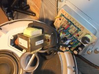
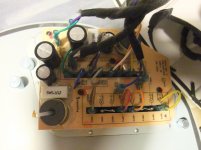
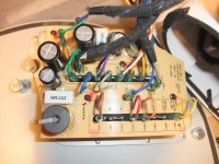
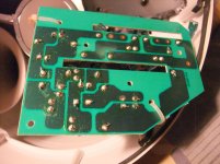
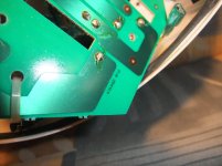
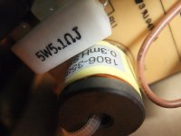
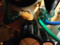
Crossover Network PCB, Bose® FreeSpace®3 Ser. II Subwoofer
here these images. Creation of Schematic is in progress.
here these images. Creation of Schematic is in progress.
Attachments
-
 Bose® FreeSpace®3 Ser. II Crossover Netw.-I.jpg985.2 KB · Views: 79
 -
 Bose® FreeSpace®3 Ser. II Crossover Netw.-II.jpg998.9 KB · Views: 88
 -
 Bose® FreeSpace®3 Ser. II Crossover Netw.-III.jpg839.5 KB · Views: 81
 -
 Bose® FreeSpace®3 Ser. II Crossover Netw.-IV.jpg1,003.8 KB · Views: 76
 -
 Bose® FreeSpace®3 Ser. II Crossover Netw.-V.jpg980.6 KB · Views: 72
 -
 Bose® FreeSpace®3 Ser. II Crossover Netw.-VII.jpg972.1 KB · Views: 64
 -
 Bose® FreeSpace®3 Ser. II Crossover Netw.-VIII.jpg980.3 KB · Views: 69
 -
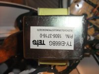 Bose® FreeSpace®3 Ser. II Transf.-II.jpg994.2 KB · Views: 70
 -
 Bose® FreeSpace®3 Ser. II Transf.-III.jpg979.6 KB · Views: 61
 -
 Bose® FreeSpace®3 Ser. II Transf.-IV.jpg881.8 KB · Views: 67
Last edited:
If you still want to make the 1Ω speakers into 8Ω speakers there is a simple kludge you can do. Instead of connecting to the 100V (PA) input on the step-down transformer, connect the amplifier (+) to the 32W input and (-) to the 100V common (-) terminal. You'll need a quick connect terminal on the (+) lead, then use the 4W tap.
Forget what the markings say, this connection will make the Model 32 appear like an 8Ω driver to the amplifier. We are now using the transformer to make an 8:1 voltage step-down to the speaker which correspondingly makes the speaker seem 8 times higher impedance to the amplifier. The power delivered by the amplifier = the power delivered to the speaker, and the transformer does the impedance transformation.
Forget what the markings say, this connection will make the Model 32 appear like an 8Ω driver to the amplifier. We are now using the transformer to make an 8:1 voltage step-down to the speaker which correspondingly makes the speaker seem 8 times higher impedance to the amplifier. The power delivered by the amplifier = the power delivered to the speaker, and the transformer does the impedance transformation.
Last edited:
Good intention but a couple mistakes here:
Doesn´t look too useful to me.
Impedance ratio is square of voltage ratio.
It will work, but speaker can only get 4W RMS there, because that´s all the winding can supply.make the 1Ω speakers into 8Ω speakers ..... connect the amplifier (+) to the 32W input and (-) to the ... common (-) terminal. ..... then use the 4W tap.
Doesn´t look too useful to me.
Sorry but no.We are now using the transformer to make an 8:1 voltage step-down to the speaker which correspondingly makes the speaker seem 8 times higher impedance to the amplifier.
Impedance ratio is square of voltage ratio.
Yes, but remember in your example maximum power is limited to 4W.The power delivered by the amplifier = the power delivered to the speaker, and the transformer does the impedance transformation.
Thanks for pointing my brain fade. As you said the voltage ratio is the square root of the impedance transformation, i.e. ~2.83:1Good intention but a couple mistakes here:
It will work, but speaker can only get 4W RMS there, because that´s all the winding can supply.
Doesn´t look too useful to me.
Impedance ratio is square of voltage ratio.
The labelling of the taps is not indicative of the power available from that tap except in the case that the transformer is connected to a 100 volt line input. The full 32 watts into 1Ω is available from the 4W tap as long as enough voltage is supplied into the 32W tap. The power that can be handled by the transformer is limited by the size of the core, not the turns ratio.Yes, but remember in your example maximum power is limited to 4W.
There is a consequence of wiring the transformer this way which is that at 32 watts into the autotransformer on the 32W tap and the speaker on the 4W tap, the 100V input tap will actually have 283 volts on it. That’s unlikely to be a problem unless someone were to put their finger on it inadvertently.
Of course a mismatched transformer won’t necessarily meet frequency response specification, which is why I called the solution a ‘kludge’. For band limited speakers such as in this example it probably doesn’t matter. I use the same kludge to run some Tannoy CPA-5 ‘shoebox’ PA speakers daisy-chained off a 200w/8Ω amp (nominally 40V) to give them ~30 watts each. It works just fine.
need help for understanding all different modes mentioned on page 8-11 under
http://warehousesound.com/r/boseFREESPACE3manual.pdf
The follow modes I understand:
1) Stereo mode (two inputs, CH-1, CH-2)
2) Mono-mode (one input, therefore "+" and "-" of both channels are connected by wires as shown in the associated figures
3) 70/100V input mode, same as 2), but with connected transformer (in this mode no stereo operation is possible)
The mode with follow term I don't understand (is even not describe in the above mentioned PDF):
DIRECT COUPLE INPUT
Is it also a mono mode, but with series connection from voice coils of the bass transducer resp. bass driver with dual voice coil ?
If yes, one jumper must go from "-" CH-1 to "+" CH-2. In this case the satellites operates also in series include the high pass and equalizer unit.
Thanks for an advice.
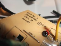
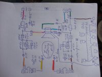
in the attachment now the schematic, maybe still with some errors. But please note: Follow isn't error resp. mistake:
1) both COM-Pins from transformer are internal connected and external connection (grey wire) goes to the voice coil PIN of bass driver for CH-2 (neg. pole, go to image No 5) and not for CH-1.
2) pos. PIN for activation of transformer (wire to secondary winding connections 25-100W) goes to pos. input of CH-1 (brown wire) and not of CH-2.
Consequence is by use of transformer in stereo mode, that no sound in both channels is audible.
Polyfuses are in series of the complete system.
Only 100 µF NP capacitor for sat high pass, but additional equalizer LCR parallel network in series to the sat speakers to attenuate the midrange area.
However - the question of my previous post #30 remains.
Attachments
-
 DSCF7972.jpg756.4 KB · Views: 134
 -
 DSCF7974.jpg770.9 KB · Views: 161
 -
 Bose® FreeSpace®3 Ser. II Driver-III.jpg978.4 KB · Views: 86
 -
 Bose® FreeSpace®3 Ser. II Crossover Netw. Connections-III.jpg979.1 KB · Views: 86
 -
 Bose® FreeSpace®3 Ser. II Driver-II.jpg982.9 KB · Views: 81
 -
 Bose® FreeSpace®3 Ser. II Crossover Netw. Connections-II.jpg996.3 KB · Views: 77
 -
 Bose® FreeSpace®3 Ser. II Crossover Netw. Connections-I.jpg940.6 KB · Views: 92
Last edited:
Various measurements in the attached images.
1) Subwoofer alone (without satellite speakers)
a. impedance plots - first image:
white: voice coil CH-1
blue: voice coil CH-2
yellow: both voice coils in parallel (wires from CH-1 to CH-2)
b. SPL plots - second and third image
white: voice coil CH-1
blue: voice coil CH-2
green: both voice coils in parallel (wires from CH-1 to CH-2)
Parallel mode of voice coils don't provide any additional SPL despite halving the impedance. This behaviour I don't understand.
The only effect in parallel mode of both voice coils I observe is a more flat plot between 60 Hz and 200 Hz.
2) Subwoofer include Sat Speakers
a) impedance plots - fourth image (only one voice coil sub, at sat "+" on 32 and C to 1):
white: CH-1
blue: CH-2
b) impedance plots - eighth image ("+" on 32,C to 4):
white: one voice coil of sub
blue: both voice coils of sub
c) impedance plots - fifth image (only one voice coil sub)
white: "+" on 32 and C to 1
blue: "+" on 32 and C to 4
d) SPL Plots - sixth image (only one voice coil sub)
white: "+" on 32 and C to 4
blue: "+" on 32 and C to 1
e) SPL Plots seventh image (only one voice coil sub)
green: "+" on 32 and C to 4
white: "+" on 32 and C to 1
blue: same as white, but polarity of Sat ("+" and "-") changed
Attachments
-
 Sub only Imp first VC, second VC both VC.jpg1,008.1 KB · Views: 62
 -
 Sub only SPL first VC, second VC both VC-II.jpg1,007.7 KB · Views: 70
 -
 Sub only SPL first VC, second VC both VC.jpg1,019.1 KB · Views: 75
 -
 SUB+SAT Imp +=32,C to 1 CH1 vs. CH2.jpg1,015.4 KB · Views: 66
 -
 SUB+SAT Imp+=32,C to 1 = white vs. C to 4 = blue.jpg1,010.2 KB · Views: 59
 -
 SUB+SAT SPL+=32,C to 1 = blue vs. C to 4 = white.jpg1,018.7 KB · Views: 74
 -
 SUB+SAT SPL+=32,C to 1 = blue+white vs. C to 4 = green.jpg1,012.8 KB · Views: 56
 -
 SUB+SAT Imp one VC, white vs. both VC, blue +=32,C to 4.jpg1,012.8 KB · Views: 61
Last edited:
- Home
- Loudspeakers
- Multi-Way
- Bose® FreeSpace® Model 32 - how do I get 4-8 Ohms ?