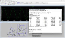
This is very similar to the old Linsley Hood amplifier, which is widely discussed here and everywhere.
The use of a diode is not explained good enough in the linked article, I have not seen it before and
the approach may be wrong.
The use of a diode is not explained good enough in the linked article, I have not seen it before and
the approach may be wrong.
Last edited:
Wouldn't any ripple on the rail have a low impedance path to the load via the diode and cap? With an SMPS (HF ripple) that might be more problematic.
Bootstrapping with a diode is the most common way to do the bootstrap - in non audio applications. Less linearity and you have to deal with the diode switching noise. You dont want those artifacts introduced in an amplifier but when driving the gate of a mosfet in a high side switch all you want is as much charge storage as you can get - and it’s better with the diode than a resistor which bleeds charge off. With the amplifier, you usually live with the charge bleeding off in the resistor instead of dealing with crap generated by the diode. If you used the diode it will work but not sound as good. Some early low-voltage single supply IC audio amps did this to get every millivolt of output swing they could. But none of those IC amps sounded very good anyway.
The diode provides a greater ~boost voltage but creates a small amount of distortion. A resistor discharges the bootstrap cap as well as charges it. This arrangement is standard on switch-mode buck converters. Ironically, a lot of boot-strap voltage is bad for rail sticking because the output gate can be driven well past saturation, so it takes time to get back to an operational voltage. A lot of, especially older, designs contain ideas that where never tested well and have issues, ie were bad ideas. The diode idea would be useful if the supply voltage was low enough to lack the gate threshold, ie like 9V total. But with a 30V supply it's easy to use a resistor and still have the required 6 or 8 volts on R7, ie about 2x the ~4V gate threshold. Also note that this amp has about 15V/10K=1.5mA VAS current, which means it will have slew problems driving the MOSFET gate capacitance. 1.5mA/1nF ~=> 1.5V/uS. So a better amp would use two resistors about 2k2 each for a 2x faster slew rate and less rail sticking. Regular MOSFETs should also have source resistors (~0.22) for thermal stability.
Thanks for answers. I suspected that there was something wrong with this scheme 🙂 You confirmed my suspicions.
By the way, how to choose the correct resistor ratio in a classic bootstrapping circuit (without a diode)? For example, in this diagram, what values should resistors R7 have and the resistor that will be installed instead of the diode?
By the way, how to choose the correct resistor ratio in a classic bootstrapping circuit (without a diode)? For example, in this diagram, what values should resistors R7 have and the resistor that will be installed instead of the diode?
A diode + resistor can be combined: it reduces the non-linearity and practically eliminates the switching noise whilst reducing the dissipation for large excursions (the cap cannot discharge into the +rail).
I think that I have an example posted on this site, but I don't remember which one; probably one of the circuits I designed for Daniel
I think that I have an example posted on this site, but I don't remember which one; probably one of the circuits I designed for Daniel
I also used a diode and resistor in series in my amplifier years ago, see pages 140...143 of Electronics World February 1996, https://worldradiohistory.com/UK/Wireless-World/90s/Electronics-World-1996-02-S-OCR.pdf Connecting a relatively big capacitor with a diode to an amplifier output without any series resistor is asking for trouble on the first peak after a volume increase.
A very interesting 3rd twist on similar non JLH circuits. I found that making the upper output into a Darlington solves some of the problems. OK, that abandons a nice, undistorted VAS current, but the end results are better.
Attachments
H
HAYK
The duty of the bootstrap capacitor is to provide a constant voltage to simulate a CCS to the driver. If you apply a diode, the capacitor is charged at Vcc. When the output goes full negative, the output will see the capacitor in series with the diode as load, 99% chance it will oscillate. When it goes back to zero the capacitor has charged Vcc+ negative output that can be max. double, hence the current through the 2 resistors is much higher now. If the bias voltage across the adjust increases considerably that the amp goes over biased if not shorted.
With a series resistor, the current increase can be controlled, and it could act as a kind of sliding bias: during the near-silent moments, the class A range is minimal, but it increases with the music level (up to a point).
Is it actually beneficial? I have no certitude, but it is worth considering
Is it actually beneficial? I have no certitude, but it is worth considering
- Home
- Amplifiers
- Solid State
- Bootstrapping with diode?

