I had a wonder about bootstrapping the supplies for an opamp in an output stage to linearize it. Then I spent way too long in LTSpice...

There's a lot going on here - the input stage and VAS are pretty standard, except perhaps that the VAS is very lightly loaded at 1mA standing current and only driving an opamp input.
There is capacitive bootstrapping to provide opamp rails that track the output voltage (no attempt at considering protection circuitry yet), and this is used in a non-inverting configuration with about 1.1 gain factor. The compensation for this was mainly trial and error and I don't claim it any good other than to allow the simulation to run(!)
The opamp rails are limited to 30V by a zener and decoupled with 100nF. Since they swing with the output there is plenty of headroom for driving the drivers/output transistors right to the rails, and the 1.1 gain factor means the VAS doesn't have to get particularly close to the rails, relaxing its requirements.
I have simulated with some ripple on the +/-45V main rails (at different frequencies to allow their effects to be identified in an FFT plot). I've also simulated reactive loading by driving the opposite end of the 8 ohm load with 10V at yet another frequency.
It turns out the OS with opamp is pretty linear (IIRC about -100dB distortion) - its able to reject the simulated reactive load by 90dB or so by itself, but the overall negative feedback loop easily knocks that down out of sight:

The fourier analysis claims 0.001495% at 1kHz (40V peak) altogether upto the 80th harmonic. You can just see the 200Hz and 500Hz breakthrough from the rails in this plot, attenuated from 1V on the rails to about 30uV at the output.
The overall gain is x 20 (26dB), and from 45V rails with 1V ripple (ie dipping to 44V) it clips at around 42V peak.
The elephant in the room is how robust can such a scheme be made, given any fault on the output risk putting 45V or more onto the opamp in various ways.
There's a lot going on here - the input stage and VAS are pretty standard, except perhaps that the VAS is very lightly loaded at 1mA standing current and only driving an opamp input.
There is capacitive bootstrapping to provide opamp rails that track the output voltage (no attempt at considering protection circuitry yet), and this is used in a non-inverting configuration with about 1.1 gain factor. The compensation for this was mainly trial and error and I don't claim it any good other than to allow the simulation to run(!)
The opamp rails are limited to 30V by a zener and decoupled with 100nF. Since they swing with the output there is plenty of headroom for driving the drivers/output transistors right to the rails, and the 1.1 gain factor means the VAS doesn't have to get particularly close to the rails, relaxing its requirements.
I have simulated with some ripple on the +/-45V main rails (at different frequencies to allow their effects to be identified in an FFT plot). I've also simulated reactive loading by driving the opposite end of the 8 ohm load with 10V at yet another frequency.
It turns out the OS with opamp is pretty linear (IIRC about -100dB distortion) - its able to reject the simulated reactive load by 90dB or so by itself, but the overall negative feedback loop easily knocks that down out of sight:
The fourier analysis claims 0.001495% at 1kHz (40V peak) altogether upto the 80th harmonic. You can just see the 200Hz and 500Hz breakthrough from the rails in this plot, attenuated from 1V on the rails to about 30uV at the output.
The overall gain is x 20 (26dB), and from 45V rails with 1V ripple (ie dipping to 44V) it clips at around 42V peak.
The elephant in the room is how robust can such a scheme be made, given any fault on the output risk putting 45V or more onto the opamp in various ways.
Last edited:
Mark, I used a low voltage (5 V) high speed video opamp that I powered off the EF3 bias voltage to linearize the OPS. It gave quite good results. I will have to dig the circuit up (will be after Wednesday next week).
That would break the functionality, the opamp rails swing well past the supply rails, and lots of compliance is needed.
Well I'm revisiting this thread as I had the idea of combining my NIC VAS concept to this opamp-linearized output stage:

So now there are 3 opamps, the first plays the role of input stage, the second the VAS and the third closes the local loop for linearizing the output stage (basically as above). The first has fixed rails, the other two have bootstrapped rails to keept them riding the signal appropriately.
In simulation at least this seems to work very well - I see 10kHz distortion figure of 0.000065% and an unholy 0.000001% for 1kHz. However I certainly don't trust the LTSpice models for opamp distortion, but it indicates the massive amount of negative feedback at work.
My simulation injects currents into the load to simulate reactance and voltages on the rails to see what the PSRR is like, and its very good as expected. Here's the 1kHz spectrum (flattop, 20ms run) showing these to have levels over 160dB down...

Of course any real manifestation of the design will be at the mercy of the input opamp's common-mode non-linearity, unless that is also bootstrapped....
Bit of a cop-out for the 2mA current sources, but I suggest using opamp current sources, and power them off the same chain that powers the input opamp, since they will have non-overlapping voltage ranges. Add suitable Vbe multiplier in place of the 1.18V voltage sources.
So now there are 3 opamps, the first plays the role of input stage, the second the VAS and the third closes the local loop for linearizing the output stage (basically as above). The first has fixed rails, the other two have bootstrapped rails to keept them riding the signal appropriately.
In simulation at least this seems to work very well - I see 10kHz distortion figure of 0.000065% and an unholy 0.000001% for 1kHz. However I certainly don't trust the LTSpice models for opamp distortion, but it indicates the massive amount of negative feedback at work.
My simulation injects currents into the load to simulate reactance and voltages on the rails to see what the PSRR is like, and its very good as expected. Here's the 1kHz spectrum (flattop, 20ms run) showing these to have levels over 160dB down...
Of course any real manifestation of the design will be at the mercy of the input opamp's common-mode non-linearity, unless that is also bootstrapped....
Bit of a cop-out for the 2mA current sources, but I suggest using opamp current sources, and power them off the same chain that powers the input opamp, since they will have non-overlapping voltage ranges. Add suitable Vbe multiplier in place of the 1.18V voltage sources.

I built a model amp of the above, limited to +/-18V supplies using NE5543A's, and a couple of output transistors, and managed to make it stable (by trial and error with a bunch of 47pF caps!). The circuit:

With the limited supply voltage I could avoid having to bootstrap the VAS and OS opamps, but I have added bootstrapping (U2) for the IS such that U1 sees is inputs, output and rails all swing together to avoid common-mode distortion and provide a ton more open loop gain.
I also simplified the VAS to a simple non-inverting stage as the NIC VAS is only required for high voltage signals. Gain is x21 with the feedback networks the same ratio for U1 (global) and U3 (VAS) stages (in order that U2's output swings the same as its input).
A problem is LTSpice with the models I have for NE553X devices won't run with more than 1 or 2 devices in a loop, so I had to change the first and last to LT1022's to get it to simulate, giving this spectrum for 1kHz, for what its worth:

In the real circuit all were NE5534A's with 47pF compensation caps (pins 5&8) added to U2 & U5 as they have unity gain. Also the real circuit has 100nF decoupling caps on each chip between pins 4 and 7.
Initially with real circuit I didn't have R14/15/16/17 and just drove the bases in parallel, so the cross-over distortion on the output of U5 was very visible and the effect of U5 in linearizing the output also very clear.
I hope to do some measurements of distortion with the real circuit at some point.
With the limited supply voltage I could avoid having to bootstrap the VAS and OS opamps, but I have added bootstrapping (U2) for the IS such that U1 sees is inputs, output and rails all swing together to avoid common-mode distortion and provide a ton more open loop gain.
I also simplified the VAS to a simple non-inverting stage as the NIC VAS is only required for high voltage signals. Gain is x21 with the feedback networks the same ratio for U1 (global) and U3 (VAS) stages (in order that U2's output swings the same as its input).
A problem is LTSpice with the models I have for NE553X devices won't run with more than 1 or 2 devices in a loop, so I had to change the first and last to LT1022's to get it to simulate, giving this spectrum for 1kHz, for what its worth:
In the real circuit all were NE5534A's with 47pF compensation caps (pins 5&8) added to U2 & U5 as they have unity gain. Also the real circuit has 100nF decoupling caps on each chip between pins 4 and 7.
Initially with real circuit I didn't have R14/15/16/17 and just drove the bases in parallel, so the cross-over distortion on the output of U5 was very visible and the effect of U5 in linearizing the output also very clear.
I hope to do some measurements of distortion with the real circuit at some point.
I had another rework of this idea, using a more standard input stage and VAS and bootstrapping the opamp as before but using the opamp supplies to power the drivers too.

The circuit can be configured with local feedback just for the VAS and IS, since the OS is very linear, or as above with the overall loop wrapping all the stages - the extra capacitive feedback from VAS to IS helps handle transients/square wave inputs as the OS slew-limits in that case

The 1kHz performance simulates well, harmonics at -112dB or lower (at 30dB output level this is 0.1ppm - of course unobtainable outside of simulation!) - the top rail rejection is excellent (note the 1V signals I inject on the rail is -158dB), and with good rail decoupling on the lower rail down at -112dB (the VAS stage is sensitive to this rail). The 7.5kHz signal is injected on the other side of the load to test the damping factor.
The raw output stage without opamp has around 0.2% THD for comparison.
I've still to play with a real manifestation of any of these circuits with real bootstrapping, alas.
The circuit can be configured with local feedback just for the VAS and IS, since the OS is very linear, or as above with the overall loop wrapping all the stages - the extra capacitive feedback from VAS to IS helps handle transients/square wave inputs as the OS slew-limits in that case
The 1kHz performance simulates well, harmonics at -112dB or lower (at 30dB output level this is 0.1ppm - of course unobtainable outside of simulation!) - the top rail rejection is excellent (note the 1V signals I inject on the rail is -158dB), and with good rail decoupling on the lower rail down at -112dB (the VAS stage is sensitive to this rail). The 7.5kHz signal is injected on the other side of the load to test the damping factor.
The raw output stage without opamp has around 0.2% THD for comparison.
I've still to play with a real manifestation of any of these circuits with real bootstrapping, alas.
I've done some actual measurements on a model O.S. with and without opamp feedback (recently received my new QA403)
Without opamp feedback around the (crude zero-bias) O.S.:

And with the NE5534A providing feedback:

Alas due to breadboard circuit there's more 50Hz harmonics than I'd like scattered in there. Anyway the improvement seems to be around 89dB in the worst harmonic (3rd) for a 250Hz signal.
Now the simulations:


Which isn't quite so impressive improvement but matches nicely.
Circuit:

The real circuit has 47p compensation cap, the Spice model NE5534A seems to lack any idea of compensation! The real transistors were MJE15030/1 but I didn't have Spice models for those.
The horrendous open-loop performance of the O.S. in the time domain:

Hope to up the supply voltage and bootstrap the opamp next.
Without opamp feedback around the (crude zero-bias) O.S.:
And with the NE5534A providing feedback:
Alas due to breadboard circuit there's more 50Hz harmonics than I'd like scattered in there. Anyway the improvement seems to be around 89dB in the worst harmonic (3rd) for a 250Hz signal.
Now the simulations:
Which isn't quite so impressive improvement but matches nicely.
Circuit:
The real circuit has 47p compensation cap, the Spice model NE5534A seems to lack any idea of compensation! The real transistors were MJE15030/1 but I didn't have Spice models for those.
The horrendous open-loop performance of the O.S. in the time domain:
Hope to up the supply voltage and bootstrap the opamp next.
So I've rebuilt the circuit, adding rudimentary biasing to the crude class B output stage, running from +/-40V or so with bootstrapped opamp supply, opamp input protection diodes, and adding components to stabilize the bootstrapping (10 ohm/10nF filter):

Running at 250Hz, 18dbV (11V peak) gets this measured response:

Which is about -106dB THD, and compares quite closely to LTSpice:

The large amounts of negative feedback at low frequencies makes the 19kHz/20kHz IMD plot very respectable - I suspect the bootstrapping of the opamp helps prevent common-mode distortion from rearing its head (-140dB from a humble opamp is surprizing - although I confess I'm not really sure what the QA403 IMD test actually measures(!):

I conclude that this approach to locally linearizing an O.S. is viable and capable of drastically reducing crossover products.
Next step will be building a complete 3-stage amp using this and finding out if this is easy to tame for stability and whether the performance can be further improved as my earlier simulations in this thread suggested.
I also need to figure out some heat-sinking for my output devices so I can change the load to a more realistic value.
Running at 250Hz, 18dbV (11V peak) gets this measured response:
Which is about -106dB THD, and compares quite closely to LTSpice:
The large amounts of negative feedback at low frequencies makes the 19kHz/20kHz IMD plot very respectable - I suspect the bootstrapping of the opamp helps prevent common-mode distortion from rearing its head (-140dB from a humble opamp is surprizing - although I confess I'm not really sure what the QA403 IMD test actually measures(!):
I conclude that this approach to locally linearizing an O.S. is viable and capable of drastically reducing crossover products.
Next step will be building a complete 3-stage amp using this and finding out if this is easy to tame for stability and whether the performance can be further improved as my earlier simulations in this thread suggested.
I also need to figure out some heat-sinking for my output devices so I can change the load to a more realistic value.
I've finally combined this idea with the NIC (negative impedance converter) based amp design in an actual physical realization and taken some measurements.
Each opamp is on a module with zeners/caps/protection/feedback network for convenience. Each of them can be floating with its power rails bootstrapped. The first module is fixed at ground and is the input stage, the middle is the NIC, floating around 65% of the output swing, and the last section is the opamp linearizing the output stage (just visible top right on heatsink). This last stage floats at about 90% of output swing.

The circuit is a simplified version of the one below (it lacks the first opamp U3, and the output stage is CFP, not EF:

The bias circuit is omitted and replaced by a self-contained variable voltage source (range 0 to 3.2V, visible centre top with blue battery). This has to be dialled in by hand (10 turn pot) to select the bias point.
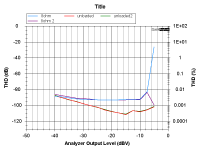
The basic distortion performance currently is about 0.0025% under load (8 ohms) for lowish levels:

(Note the levels are at the input of the amp and the gain somewhere around 25dB (depending on compensation network changes))
Currently I'm limited to 0.5A current limited supply and I'm still trying various compensation methods. I don't want to switch to the beefy supply until I'm happy its not going to burst into oscillation!
I've also experimented with breaking the thing into two separate parts, IS+VAS (with one feedback loop) and OS+opamp (separate feedback loop):

This is easier to stabilize, but the distortion is limited by the output section. I'm aware the breadboard lash up is problematical as adding more ground wires has reduced distortion, and I want to fit a proper busbar to the setup to reduce ground issues due to lots of contact resistances along the chain.
Each opamp is on a module with zeners/caps/protection/feedback network for convenience. Each of them can be floating with its power rails bootstrapped. The first module is fixed at ground and is the input stage, the middle is the NIC, floating around 65% of the output swing, and the last section is the opamp linearizing the output stage (just visible top right on heatsink). This last stage floats at about 90% of output swing.
The circuit is a simplified version of the one below (it lacks the first opamp U3, and the output stage is CFP, not EF:
The bias circuit is omitted and replaced by a self-contained variable voltage source (range 0 to 3.2V, visible centre top with blue battery). This has to be dialled in by hand (10 turn pot) to select the bias point.
The basic distortion performance currently is about 0.0025% under load (8 ohms) for lowish levels:
(Note the levels are at the input of the amp and the gain somewhere around 25dB (depending on compensation network changes))
Currently I'm limited to 0.5A current limited supply and I'm still trying various compensation methods. I don't want to switch to the beefy supply until I'm happy its not going to burst into oscillation!
I've also experimented with breaking the thing into two separate parts, IS+VAS (with one feedback loop) and OS+opamp (separate feedback loop):
This is easier to stabilize, but the distortion is limited by the output section. I'm aware the breadboard lash up is problematical as adding more ground wires has reduced distortion, and I want to fit a proper busbar to the setup to reduce ground issues due to lots of contact resistances along the chain.
Attachments
Last edited:
- Home
- Amplifiers
- Solid State
- bootstrapped opamp to linearize an output stage