Would I be right in assuming the 'section length' is measured from the front baffle to center partition for the closed end and center partition to rear baffle respectively?
This is what I pick up from reading the app notes anyhow - although the default values seem rather small unless they are in the Y axis (which would make them relative to the top of the closed end and bottom of the cabinet) - I'm presuming them to be on the X axis...but if they are on the Y axis, then that changes everything ...

This is what I pick up from reading the app notes anyhow - although the default values seem rather small unless they are in the Y axis (which would make them relative to the top of the closed end and bottom of the cabinet) - I'm presuming them to be on the X axis...but if they are on the Y axis, then that changes everything ...
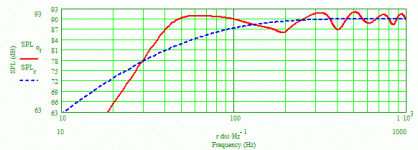
The Sections lengths are measured along the line's length (Y-axis) from the closed end to the open end, not along the depth (X-axis). So that does change everything. You can model any type of TL you want, tapered, ML-TL, ML-TQWT or traditional using the ML-TL Corner worksheet, although you'll need to use the Sections worksheet if the line is folded more than once or folded and tapered in order to make the modeling as accurate as possible. With the ML-TL Corner worksheet the number of required entries to define the line are less numerous. For the M6A I modeled a line 72" long with a cross-sectional area of 8" x 8" throughout the line and the terminus, and the driver's center located 14" from the closed end of the line. I used a stuffing density of 1 lb/cu.ft., with stuffing in the first 37" of the line. I've attached the system response graph in which you can see how lumpy the response is, very typical of a traditional, non-tapered line. If the stuffing length is increased, the response can be smoothed out but with a serious detriment to F3.
Paul
Paul
Would I be right in assuming the 'section length' is measured from the front baffle to center partition for the closed end and center partition to rear baffle respectively?
This is what I pick up from reading the app notes anyhow - although the default values seem rather small unless they are in the Y axis (which would make them relative to the top of the closed end and bottom of the cabinet) - I'm presuming them to be on the X axis...but if they are on the Y axis, then that changes everything ...
An externally hosted image should be here but it was not working when we last tested it.
Attachments
Paul - and you're going to kill me : I'm beginning to think, and call me mad....
Back to Dayton DC160s, at 33Hz in an MLTL, passed low at appx. 500Hz
HiVi M3N in a separate little compartment, and crossed again at 2.5kHz before the ugly cone break up...
Highs then to Visaton tweeter.
Works out, cost-wise, about the same as the two M6As...?
Back to Dayton DC160s, at 33Hz in an MLTL, passed low at appx. 500Hz
HiVi M3N in a separate little compartment, and crossed again at 2.5kHz before the ugly cone break up...
Highs then to Visaton tweeter.
Works out, cost-wise, about the same as the two M6As...?
I can't give you any advice on what tweeter to use or midrange to use or any crossover advice. If you want help on an ML-TL for a DC160 (which specific model?), I'm available.
Paul
Paul
Paul - and you're going to kill me : I'm beginning to think, and call me mad....
Back to Dayton DC160s, at 33Hz in an MLTL, passed low at appx. 500Hz
HiVi M3N in a separate little compartment, and crossed again at 2.5kHz before the ugly cone break up...
Highs then to Visaton tweeter.
Works out, cost-wise, about the same as the two M6As...?
Many thanks paul - I'm fairly au-fait with filtering, and paying a little attention to the response curves should sort out any nastiness. I'll try to model this myself - if one is designing a ML-TL, would it be correct to view half of the box (the top half) as the 'closed end' and the bottom half as the 'open end?
L
L
The closed end, no matter what type of TL you're designing, is the end at which the driver is most closely located, and the optimum location for the driver is usually around 20% of the line's length from the closed end (the driver can be located closer to or further away from the closed end, however). The open end simply indicates where the terminus or mass-loading port is located. When I model ML-TLs, the resulting location of driver and port just naturally ends up with approximately the first half of the line containing stuffing, but it doesn't have to be that way. Your modeling may lead you to place stuffing in less of the line or more of the line.
Paul
Paul
Many thanks paul - I'm fairly au-fait with filtering, and paying a little attention to the response curves should sort out any nastiness. I'll try to model this myself - if one is designing a ML-TL, would it be correct to view half of the box (the top half) as the 'closed end' and the bottom half as the 'open end?
L
Cheers Paul,
I'm going to model that DC160s in a number of different types of lines (or try, at least) - response above 200Hz isn't awfully important if I'm considering a separate midrange, as that can be taken care of itself...but this brings in all manners of crossover issues and complex impedances...
Give me a Fostex FE127!
As your plots show, with a ~72" line (for the M6A, the DC160s will be longer due to Fs of 33Hz) - there is a pronounced low frequency SPL increase, but it all goes wrong at about 200Hz - the M3N can be crossed over at 150ish in that case, relegating the DC160 to woofer duties only.
- Status
- This old topic is closed. If you want to reopen this topic, contact a moderator using the "Report Post" button.
- Home
- Loudspeakers
- Multi-Way
- Bonjour de Montréal - Budget Dayton DIY setup...