I have a bogen CHB35a that i have had for a few years and finally decided to start a project for the first time.
1. orderd new all new tubes
2. added grounded cord
3. wired mic 1 with 1/4" jack
4. connected 8 ohm speaker plugged up guitar and played for about an hour the first time sounded great nice, clean with lots of power (only took vol to 50% a little at a time over the hour)
5. Second trial same result sounded great no notable bad sounds.
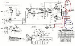
6. removed 70v lead from OT to 3 prong speaker impedance connectors and insulated the end.
7. removed "rem #1" and "rem # 2" leads to screw terminals on back of the chassis leaving all the original resistors in line.
8. removed black/red 25v lead from OT from screw terminal on back of chassis and insulated the end..... According to "S&G Carter" the this lead is supposed to be grounded through a 39k and 10k resistor to ground that was a part of the wiring for the "WMT-1" and "Tape Booster" connectors that are shown in the schematic... only my chassis does not have these connectors and never did, it was just connected strait to the screw terminal on the back of the chassis. I insulated it and that was it.
9. fired the amp back up only to hear a loud hum followed by a high squeal (with vol at 0 ) and no output from the guitar. So I quickly shut off the unit.
Would this have anything at all to do with what I have done here?
I realize the amp needs recapping and could fault at anytime without this being done, and plan to recap to get it back to stock before any serious mods.
I attached a copy of the schematic with the removed items highlighted
1. orderd new all new tubes
2. added grounded cord
3. wired mic 1 with 1/4" jack
4. connected 8 ohm speaker plugged up guitar and played for about an hour the first time sounded great nice, clean with lots of power (only took vol to 50% a little at a time over the hour)
5. Second trial same result sounded great no notable bad sounds.
6. removed 70v lead from OT to 3 prong speaker impedance connectors and insulated the end.
7. removed "rem #1" and "rem # 2" leads to screw terminals on back of the chassis leaving all the original resistors in line.
8. removed black/red 25v lead from OT from screw terminal on back of chassis and insulated the end..... According to "S&G Carter" the this lead is supposed to be grounded through a 39k and 10k resistor to ground that was a part of the wiring for the "WMT-1" and "Tape Booster" connectors that are shown in the schematic... only my chassis does not have these connectors and never did, it was just connected strait to the screw terminal on the back of the chassis. I insulated it and that was it.
9. fired the amp back up only to hear a loud hum followed by a high squeal (with vol at 0 ) and no output from the guitar. So I quickly shut off the unit.
Would this have anything at all to do with what I have done here?
I realize the amp needs recapping and could fault at anytime without this being done, and plan to recap to get it back to stock before any serious mods.
I attached a copy of the schematic with the removed items highlighted
Attachments
- Status
- Not open for further replies.