Guitar Amp, Right?
Welcome to the Tubes / Valves portion of diyAudio!
(There is also an Instruments & Amps for Electric Guitar Amps on diyAudio)
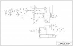
You may want to check your actual circuit wiring versus the schematic.
The schematic will not work well, and probably not at all.
Already mentioned by audiopro, no plate resistors on the first 2 stages.
500k volume pot, versus 12AX7 Miller Effect Capacitance will roll off the high frequencies very severely.
One phase inverter cathode has 2.2k self bias resistor.
One phase inverter cathode has 470 Ohm self bias resistor.
The plate voltage, gain, and current will be way different.
Not a good way to run a phase inverter.
100k driving the top phase inverter, another rapid high frequency roll off.
R10, R20, R19, and R17 do not work well together. Perhaps the intent was to create negative feedback from the output transformer secondary.
Needs complete redesign for that triode.
C13, 1.5nF is not nearly enough capacitance.
Where did the schematic come from?
Is it a composite of more than one schematic?
I am getting tired. Thats all for now.
Welcome to the Tubes / Valves portion of diyAudio!
(There is also an Instruments & Amps for Electric Guitar Amps on diyAudio)
You may want to check your actual circuit wiring versus the schematic.
The schematic will not work well, and probably not at all.
Already mentioned by audiopro, no plate resistors on the first 2 stages.
500k volume pot, versus 12AX7 Miller Effect Capacitance will roll off the high frequencies very severely.
One phase inverter cathode has 2.2k self bias resistor.
One phase inverter cathode has 470 Ohm self bias resistor.
The plate voltage, gain, and current will be way different.
Not a good way to run a phase inverter.
100k driving the top phase inverter, another rapid high frequency roll off.
R10, R20, R19, and R17 do not work well together. Perhaps the intent was to create negative feedback from the output transformer secondary.
Needs complete redesign for that triode.
C13, 1.5nF is not nearly enough capacitance.
Where did the schematic come from?
Is it a composite of more than one schematic?
I am getting tired. Thats all for now.
Last edited:
Someone can tell me if there's any mistakes on this schematic?
Yes there are. Tell us why you want to modify the original Bogen circuit, what your goal is and how you plan to accomplish that. Then we can try to point you in the right direction.
One phase inverter cathode has 2.2k self bias resistor.
One phase inverter cathode has 470 Ohm self bias resistor.
The plate voltage, gain, and current will be way different.
Not a good way to run a phase inverter.
That part is correctly copied from the Bogen diagram so I assume it is as intended by the original designer. With a paraphase it's not necessary to have equal gain. It may very well be that it provides equal signals at the grids of the output tubes.
Build it the way Pete drew it. You have cut-off essential bits, made absurd connections. I know Pete did not post it with all those mistakes. If you are going to make a mess, blot out his name.
You might even want to find the page where he talks about it.
Here's his 2015 version, with plate resistors and other essentials.
Hoffman Amplifiers Forum: bogen cha-20 hack
https://el34world.com/Forum/index.php?action=dlattach;topic=18231.0;attach=49149
You might even want to find the page where he talks about it.
Here's his 2015 version, with plate resistors and other essentials.
Hoffman Amplifiers Forum: bogen cha-20 hack
https://el34world.com/Forum/index.php?action=dlattach;topic=18231.0;attach=49149
Attachments
Last edited:
Well, at first the amp was not working so i remplace the power supply caps and add a resitor to lower the voltage a little bit. It worked with a guitar but with distortion so i remplace all the caps with this modification and it was worse. I check carefully the schematic and the amp and found a 10K resistor on the power supply not on the schematic so i lowered the voltage too much. Ok with the version 2 it should work but C13 is still not correct. Maybe it is better to put it in his original state and check all voltages this time. Regards.
Last edited:
Yes. That schematic in Post # 6 is much better.
I did forget that this is a Guitar Amp.
So . . .
It does not require equal gain in the phase splitter.
But it is not just gain that is different, it is the difference with 470 Ohms versus 2,200 Ohms in the cathodes that gives very different self bias voltage and different plate currents. And that gives a very different harmonic distortion mix.
The correct schematic makes the negative feedback more correct, does not have a resistor from cathode to plate.
I need to stay away from Guitar amps, at least when it is getting late for me, like it is now.
Good luck getting it to work as it was designed.
> 470 Ohms versus 2,200 Ohms in the cathodes that gives very different self bias voltage and different plate currents.
R19 (in the plan in post #6; the other plan has it connected wrong) makes the operating points nearly the same in both halves of V2. Note plate and cathode voltages within a few percent one to the other.
R19 (in the plan in post #6; the other plan has it connected wrong) makes the operating points nearly the same in both halves of V2. Note plate and cathode voltages within a few percent one to the other.
PRR,
Good point!
I did not see that, and I did not calculate the 150k and 470 Ohm 319:1 divider of the 350V B+, that provides most of that triode of the 12AX7's bias voltage.
That 3 resistor combination gets all the 100k negative feedback resistor to apply all its current to R19, 470 Ohm, and cathode impedance of the 12AX7 (so there is no series split resistor required for the cathode circuit, and so no bypass cap across the top resistor of the traditional cathode split resistor combo).
I never noticed or remembered that configuration before.
- Home
- Live Sound
- Instruments and Amps
- Bogen CHA 20 hack