Hello all,
I am having this idea to simplify the original Cordell's Super Gainclone schematics. In particular, I want to get rid of servo circuit and add capacitor instead.
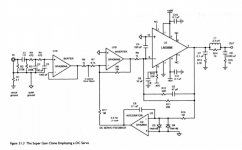
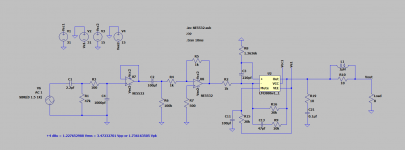
Attached are the original schematics from the book, my version, and LTSpice simulation file.
Any comments are welcome.
I am having this idea to simplify the original Cordell's Super Gainclone schematics. In particular, I want to get rid of servo circuit and add capacitor instead.
Attached are the original schematics from the book, my version, and LTSpice simulation file.
Any comments are welcome.
Attachments
Theory or practical?
Get the 3886 first, in short supply, if you want to be practical.
Theory? Waste of time, most of the tweaks are known, and useless without the chips to try on.
Latest news is delivery, maybe, in 2024.
Enjoy.
Get the 3886 first, in short supply, if you want to be practical.
Theory? Waste of time, most of the tweaks are known, and useless without the chips to try on.
Latest news is delivery, maybe, in 2024.
Enjoy.
You can put a ~22uF cap in series with R9 (1k) (R2 in simulation) and drop the servo (and drop U10 (U8 sim)). It's possible a ~20K to ground (+ cap?) on the positive input (pin 10) may improve the offset. There is a DIYA thread (~LTC Spice) about bad spice models of the LM3886. I think that model has a nasty phase inversion when overdriven but it's OK if you stay below clipping. C4 (C3 sim) worries me but whatever works?
Pushing the loop gain on chip-amps is the main reason they fail, so I'm not fond of the "super gain" idea. More than once, I have found that a chip-amp can sound very good if you back off the feedback.
Pushing the loop gain on chip-amps is the main reason they fail, so I'm not fond of the "super gain" idea. More than once, I have found that a chip-amp can sound very good if you back off the feedback.
Last edited: