You need to look up & study carefully what is EMF.
EMF is usually measured in Volts but they are NOT the same thing. Please don't expect me to teach Electrical Eng. 101
What we are discussing is complicated by the fact that IF a current flows, it generates a magnetic field too.
Michael Faraday explained all this too.
Which opposes the inducing magnetic field.
I would like to thank the members of the diyaudio forum who invite me, like DF96 and kgrlee, to learn the basics of basic physics, for their kindness to me and their anxiety about my knowledge.You need to look up & study carefully what is EMF.
However, I should point out that:
- my professors at university were not all incompetent
- my employer did not identify any serious deficiencies in the circuits I designed
- tell a contradictor that he is ignorant contravenes the rules of etiquette of the web, is counterproductive and is irrelevant when one does not know him.
It is always measured in Volt.EMF is usually measured in Volts but they are NOT the same thing.
They are not the same thing as what ?
I don't.Please don't expect me to teach Electrical Eng. 101
I tried to explain that in the other thread, including the fact that the induced magnetic field is in opposition to the first one and decreases its effect.What we are discussing is complicated by the fact that IF a current flows, it generates a magnetic field too.
Michael Faraday explained all this too.
It is not so complicated, do you know "feedback" ?
I have a question about push-pull VAS. When I asked a fellow diyAudio member a question about his designs, he commented, inter alia, that a push-pull VAS required the use of offset correction via op amp which I presume is a DC servo. I read again the relevant chapters in Bob's book and did not see anything which indicated such. Perhaps I missed it or perhaps it is obvious to all but a newbie such as myself. I was wondering if Bob had views on this and if indeed a servo is required or recommended then perhaps a sentence or two to that effect might be useful in the next iteration of the book. What are the disadvantages of a push-pull VAS (other than a modest part count increase)?
I have a question about push-pull VAS. When I asked a fellow diyAudio member a question about his designs, he commented, inter alia, that a push-pull VAS required the use of offset correction via op amp which I presume is a DC servo. I read again the relevant chapters in Bob's book and did not see anything which indicated such. Perhaps I missed it or perhaps it is obvious to all but a newbie such as myself. I was wondering if Bob had views on this and if indeed a servo is required or recommended then perhaps a sentence or two to that effect might be useful in the next iteration of the book. What are the disadvantages of a push-pull VAS (other than a modest part count increase)?
Hi SGK,
A push-pull VAS does not require a dc servo for offset control. If the push-pull VAS is implemented properly, offset properties of the amplifier should be no different than those of an amplifier that uses a single-ended VAS. Offset in either kind of amplifier is usually determined by the design of the input stage. With either type of amplifier, a DC servo usually improves DC offset.
Cheers,
Bob
When the input stage contains two differential amplifiers, one diffamp driving the "push" half of a push-pull VAS, and the other diffamp feeding the "pull" half of a push-pull VAS,
then mismatches between the two diff amps can result in DC offset at the output. This is one reason why some manufacturers use resistor loads and even resistor tail-current "sources": because precision resistors (1% or better) put a known upper bound upon the mismatch between the two circuit halves. Active current sources are more variable: Vbe/R has two sources of variability; (N*Vdiode - Vbe)/R has N+2 sources of variability. And active loads are even worse since their mismatch gets amplified onto the output. This is why you often see gain-throttling resistors across active loads, such as the 4.7K "RLoad" in Bob's 2016 Burning Amp presentation.
The offset comes from the input stage, not from the push-pull VAS.
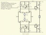
Apt, for example, has a single LTP input stage which drives a push-pull VAS. It's in Bob's book, Figure 7.14. If (R3 is tightly matched to R6), and (R4 is tightly matched to R5), and (Q7 and Q8 have similar Vbe and similar Beta), then the IPS + push-pull VAS contributes very little DC offset.
However, I personally think it's a wise precaution to include a DC servo anyway. It's DIY, the (small) extra cost is completely irrelevant. We are not trying to compete on price against Samsung!
then mismatches between the two diff amps can result in DC offset at the output. This is one reason why some manufacturers use resistor loads and even resistor tail-current "sources": because precision resistors (1% or better) put a known upper bound upon the mismatch between the two circuit halves. Active current sources are more variable: Vbe/R has two sources of variability; (N*Vdiode - Vbe)/R has N+2 sources of variability. And active loads are even worse since their mismatch gets amplified onto the output. This is why you often see gain-throttling resistors across active loads, such as the 4.7K "RLoad" in Bob's 2016 Burning Amp presentation.
The offset comes from the input stage, not from the push-pull VAS.
Apt, for example, has a single LTP input stage which drives a push-pull VAS. It's in Bob's book, Figure 7.14. If (R3 is tightly matched to R6), and (R4 is tightly matched to R5), and (Q7 and Q8 have similar Vbe and similar Beta), then the IPS + push-pull VAS contributes very little DC offset.
However, I personally think it's a wise precaution to include a DC servo anyway. It's DIY, the (small) extra cost is completely irrelevant. We are not trying to compete on price against Samsung!
Attachments
When the input stage contains two differential amplifiers, one diffamp driving the "push" half of a push-pull VAS, and the other diffamp feeding the "pull" half of a push-pull VAS,
I thought we covered this at length just a few weeks ago. The 4.7k's limit the DC gain so the offsets at the output are limited. Without them the first stage gain can be 100's even 1000's and the output offset can rail. I personally advocate thermally tied pairs or actual diff-pairs in the input with old fashion offset pots rather than servos, here one could suffer more DC gain, say 47k resistor, with a simple offset pot in one of the CM's. Even the crude Vos pot on my old Hafler 220 kept the output <50mV for years of service.
In practice, if the diff pairs are matched and thermally coupled, you can easily achieve DC offsets less than 10 mV as long as you also match the PNP and NPN betas. With good matches in the quad, >5 mV DC offset is common. That's assuming the amplifier is well designed of course!
Matching all those transistors is a PITA, big time! However, the results are worth it if the amplifier is yours. The low DC offset also corresponds to lowest distortion, which shouldn't surprise anyone here.
-Chris
Matching all those transistors is a PITA, big time! However, the results are worth it if the amplifier is yours. The low DC offset also corresponds to lowest distortion, which shouldn't surprise anyone here.
-Chris
In practice, if the diff pairs are matched and thermally coupled, you can easily achieve DC offsets less than 10 mV as long as you also match the PNP and NPN betas. With good matches in the quad, >5 mV DC offset is common. That's assuming the amplifier is well designed of course!
Matching all those transistors is a PITA, big time! However, the results are worth it if the amplifier is yours. The low DC offset also corresponds to lowest distortion, which shouldn't surprise anyone here.
-Chris
You mean product of balance? Who would have thought.
Hi David,
Yupper. That is exactly right, and the balancer is exactly what I use to match transistors.
-Chris
Yupper. That is exactly right, and the balancer is exactly what I use to match transistors.
-Chris
you need to trim with a THD analyzer if that's your goal
it should surprise anyone knowing the different mechanisms that can cause DC offsets and that they don't completely overlap with with the normalized current density that would equate the gm Taylor series terms
it may be close for some devices, their process parameter correlations/spreads - but its not guaranteed
then there is the Z (in)balance seen at the +/- inputs...
you need to trim with a THD analyzer if that's your goal
or use high enough loop gain, degeneration that input diff pair nonlinearity is never exercised by audio signals within the amp's clipping limits
The low DC offset also corresponds to lowest distortion, which shouldn't surprise anyone here.
it should surprise anyone knowing the different mechanisms that can cause DC offsets and that they don't completely overlap with with the normalized current density that would equate the gm Taylor series terms
it may be close for some devices, their process parameter correlations/spreads - but its not guaranteed
then there is the Z (in)balance seen at the +/- inputs...
you need to trim with a THD analyzer if that's your goal
or use high enough loop gain, degeneration that input diff pair nonlinearity is never exercised by audio signals within the amp's clipping limits
Last edited:
I think we would agree. As long as the LTP is matched and in thermal contact, and as long as you don't throw off the balance (DC servo acting here, or a pot), the LTP will do it's job properly and leave you with the best signal performance, including low THD. Once you start pushing the balance of that pair off, everything goes downhill.
I know of a couple places where you can correct DC offset, which is the right one? All I know is that the LTP is not where to correct for DC balance.
-Chris
I know of a couple places where you can correct DC offset, which is the right one? All I know is that the LTP is not where to correct for DC balance.
-Chris
we agree again.the LTP is not where to correct for DC balance.
Balance the LTP, that is for currents and voltages and temperatures. And keep it balanced. Look elsewhere for the reason for the excessive output offset.
Thanks all
Is it such a pain? I purchased a Peak Atlas DCA Pro. Matching from a batch seemed rather simple. Or am I missing something important?
Are there disadvantages to a push-pull VAS? Difficulties implementing VAS protection etc?
Matching all those transistors is a PITA, big time!-Chris
Is it such a pain? I purchased a Peak Atlas DCA Pro. Matching from a batch seemed rather simple. Or am I missing something important?
Are there disadvantages to a push-pull VAS? Difficulties implementing VAS protection etc?
Isn't the additional offset because we removed the evil capacitor from the FB shunt circuit?
That capacitor allowed for 100% DC feedback. Now we don't have that and offset is worse.
Then shouldn't we focus our attention here where the problem lays?
That capacitor allowed for 100% DC feedback. Now we don't have that and offset is worse.
Then shouldn't we focus our attention here where the problem lays?
DC servo vs evil electrolytic capacitor
At the end of the day, a DC servo circuit may cost less than a high-quality evil electrolytic capacitor. Dual JFET op amps are very inexpensive, and the passives associated with a DC servo are extremely inexpensive. A DC servo implemented with SMT may very well take up less board area than the quality evil electrolytic. If the use of a DC servo reduces the need for component matching, that is a further savings in cost.
Cheers,
Bob
No, the DC offset should be corrected in the Vas or "pre-driver" stages. Once the LTP is back in balance, you have things sorted.
Hi SGK,
Nope, that is quite useless. Transistor beta is extremely temperature sensitive. Both die should be kept as close to the same temperature as reasonably possible. Measuring one at a time can only be done with all the parts held at some constant temperature and thermally stabilized. Let's use 25 °C like the manufacturers do. But wait! That is both expensive and time consuming.
I use a jig I put together that creates a LTP out of the two DUTs. They are thermally connected and isolated from the surrounding air. Once they have stabilized thermally (no escape from that, and the time it takes - sorry), you simply measure the difference potential between the collectors. The best match will be very close to zero mV. With the jig I use, the collector loads are 100R 0.1%, and the base resistors to common are 10K 0.1% also. These are available and are not extremely expensive. The tail current is provided by a constant current source that is variable made with a BJT transistor and red LED (3 mm) that pokes through the hole in the TO-126 BJT. The current is reasonably constant and will do fine for this type of testing. Mine covers 100uA to about 10mA, although you can add the resistors in the emitter circuit for higher currents. I think it covers just about any reasonable situation you need to deal with. The main supplies are bipolar approx 10 VDC, but you can vary that within reasonable limits. There is both a PNP type LPT and NPN also. I use the Mill-max header sockets that are suitable for new transistors only. Soldered leads will destroy the socket.
Matches made this way demand that any emitter degeneration resistors be matched or they will throw off your matched pair. I speak from experience on this. A member here designed a PCB that seems to work well. PM me if you are interested and I'll try to find the posts for you on this thing. Simple concept, the null detection device need not be calibrated.
-Chris
I have had pretty good success doing at home, what semiconductor companies do on their production test floors: blast the DUT with super high velocity, carefully temperature controlled, air. One of these, at home, on the cheap. Especially when testing SMD devices, where it isn't possible to tightly clamp two transistors together, thermostream is pretty much your only option.
If you set your curve tracer to pulse mode, with duty cycle less than 2% (as all semiconductor test floors do), there is very little self-heating. What little heating there is, gets immediately transported away by the high velocity air. The junction temperature equals the air temperature, plus epsilon. UnitLeft and UnitRight are maintained at exactly the same temperature, because they are immersed in identical, parallel, airstreams.
_
Attachments

Hi Mark,
That looks interesting, but I would still like to leave as little to chance as possible. I generally force the two transistors together, covered with a bit of closed cell foam hollowed out for the pair and cover that with a larger box (kills air currents and improves things a lot). Using your method probably could be done with a hand heater set to low and full open air flow. The actual temperature isn't as important as the fact that the two transistors are held at the same temperature. I'd be a touch wary of operating the DUTs at temperatures well above their normal operating range.
If you are careful and use only tweezers to place transistors, allow the group of parts to reach equilibrium with the air temperature in the room. Sort using the metre function or whatever tester you like at the time. Use this to presort the transistors into groups of similar beta. Then test in the balancing jig (matcher) and group the best balanced pairs. You will notice that you have some parts that should have been in different groups. Testing singly isn't that accurate or reliable when you are creating tight matched parts.
The factory only warrants that their matched pairs are within 5%. With the jig you will be getting matches < 1%. That, is a big difference.
-Chris
The only way to test two SMD transistors simultaneously (call this "matching" if you like) is with sockets. The only way to ensure the two DUTs are at the same temperature, is to immerse them in equal temperature, high velocity streams of fluid. I like to use air as my fluid. The temperature of the airstreams can be "room" if you so choose; as long as the two streams are identical. Pulse testing at low duty cycle, helps a lot.
How variable is the air temp in your home? I lay all the devices down on my desk for a minute or two, handle the devices only with the clip leads on the DCA Pro and can test a dozen or more in a minute. Is self-heating that variable in the few seconds it takes to get a reading? (I guess controlling the taking of readings at identical times from connection is more challenging - I chose to move quickly on the grounds that dilly dally was a big variable.) I would have thought the temp impact would be minimal but if I should do this sort of thing even more carefully on my next build then do please send me some links. It sounds like I have only passed the first screening but I found for my astx SA2014 build I was able to gather enough transistors with identical measured hfe from the my purchased batches for the build despite the fact that the batches showed wide variability overall. Perhaps mere luck or stupidity.
It has occurred to me that matching SMD would be a lot more challenging and demand a rig of some description.
So you match transistors and resistors, good oh. Do you, Chris, then abandon the cap at the feedback network while still not implementing to a DC servo? (This is getting a bit far away from my original questions regarding push-pull VAS but so long as people don't mind...)
PS: when I had the transistors sorted into hfe buckets and selected the bucket for use I measured all of those ones again. The readings remained consistently the same for all in the bucket.
Last edited:
- Home
- Amplifiers
- Solid State
- Bob Cordell's Power amplifier book