To separate the tail from the capacity CCS 1 kOhm is not enough. The resistance of the resistor should be chosen so that the voltage at the collector CCS remained at approximately 10 V.
Why 10V?
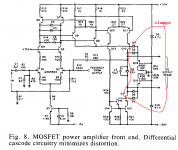
I've been won over to the Boosted Supply Rails design approach (Bob Cordell's 1st edition, 2nd page of chapter 16). It's more or less mandatory when using a MOSFET output stage because of the enormous Vgs drop in the output source follower transistors. But read what Bob has to say about the other advantages: they apply to all-BJT amplifiers as well. In particular, boosted rails make it very easy to use cascoded current sources (and cascoded 2nd stage ("VAS")). They also make it easy to install clamp diodes which prevent misbehavior during clipping; clamp supplies are simple zeners plus emitter followers, figure below.
As Bob points out a few pages later, boosted supply rails are especially easy when the power transformer is a toroid. Just add your own boost windings! 22 AWG wire handles 0.5 amps easily, while a two channel amplifier's IPS and VAS draw less than 100mA total. As an added bonus, the boosted supplies can be much more heavily filtered than the output stage's rails, improving the PSRR greatly. Even Douglas Self encourages this kind of modification (6th edition, Fig 26.19). Yet another example of a design improvement that DIYers can make {because labor is free!} but commercial manufacturers cannot. Yay team.
So: I'm sticking with no-feedback, cascode current sources using shunt reference ICs like the LM4041 ($0.30) to generate the base voltages.
Attachments
One advantage about a boosted IPS/VAS supply, is you can control which stage the clipping happens.
So where should the clipping happen, in the IPS/VAS or in the OPS?
I would assume the stage that handles overload and recovery better, which I think is the IPS/VAS, since it can recover faster than the OPS.
Pioneer used a lot of boosted supply designs, so the auction market is a good place to find suitable diy transformers.
Last edited:
To select this resistor value a little more, but CCS leave 10 volts for normal operation.Why 10V?
This circuitry can also be improved and achieve 0.000,15% at 150 W / 8 Ohm at a frequency of 20 kHz.http://www.diyaudio.com/forums/attachments/solid-state/586354d1481992152-bob-cordells-power-amplifier-book-clamp_me_seymour.png
http://www.diyaudio.com/forums/atta...1463048491-several-schemes-master-donetsk.jpg
http://www.diyaudio.com/forums/attachments/solid-state/548676d1463048739-several-schemes-9_10-.jpg
http://www.diyaudio.com/forums/solid-state/290970-several-schemes.html#post4711062
I've been won over to the Boosted Supply Rails design approach (Bob Cordell's 1st edition, 2nd page of chapter 16). It's more or less mandatory when using a MOSFET output stage because of the enormous Vgs drop in the output source follower transistors. But read what Bob has to say about the other advantages: they apply to all-BJT amplifiers as well. In particular, boosted rails make it very easy to use cascoded current sources (and cascoded 2nd stage ("VAS")). They also make it easy to install clamp diodes which prevent misbehavior during clipping; clamp supplies are simple zeners plus emitter followers, figure below.
As Bob points out a few pages later, boosted supply rails are especially easy when the power transformer is a toroid. Just add your own boost windings! 22 AWG wire handles 0.5 amps easily, while a two channel amplifier's IPS and VAS draw less than 100mA total. As an added bonus, the boosted supplies can be much more heavily filtered than the output stage's rails, improving the PSRR greatly. Even Douglas Self encourages this kind of modification (6th edition, Fig 26.19). Yet another example of a design improvement that DIYers can make {because labor is free!} but commercial manufacturers cannot. Yay team.
So: I'm sticking with no-feedback, cascode current sources using shunt reference ICs like the LM4041 ($0.30) to generate the base voltages.
Hi Mark,
I actually used the boosted rail approach when I did my MOSFET power amplifier with error correction. In that design I did indeed use a cascoded 2T VAS and Baker clamps, all made possible by the increased headroom. Although somewhat related to the large maximum Vgs needed by the MOSFETs, I think it also made the error correction approach a bit less consumptive of headroom as well.
Since the VAS was push-pull, I did not have to use a VAS current source load. I used Miller Input Compensation, so I also did not have a Miller capacitor closing the loop at high frequencies around the cascoded 2T VAS (that surely would have been asking for local instability). Instead, I compensated the MIC compensation loop with some minor lag-lead compensation. This did not hurt performance much, since that loop can be fairly wideband compared to the amplifier's global feedback loop.
I have wound auxilliary secondaries on numerous toroids, in one case four of them to provide boosted rails and +/-15V rails for lower voltage auxilliary circuits like DC servos and protection circuits. It can be laborious, that goes with the DIY territory.
A poor man's approach to better filtered "boosted" rails with less boost is to just use a separate bridge rectifier and modest reservoir capacitors for the earlier stages in the amplifier. This keeps the heavy-duty ripple of the main rails away from those circuits and also keeps those "boosted" rails from being dragged down when the main rails sag under brief heavy loads. It does not do a whole lot of effective boost under continuous power testing conditions, however. Maybe a volt or so, though.
Cheers,
Bob
10 V referenced to power supply rail or ground ? And why 10 V ?To separate the tail from the capacity CCS 1 kOhm is not enough. The resistance of the resistor should be chosen so that the voltage at the collector CCS remained at approximately 10 V.
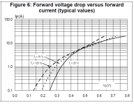
Use them newfangled field effect rectification diodes from ST and get another half a volt.
Interesting find Mark! I notice that these devices have relatively high reverse leakage, but that's probably not going to be an issue in power supplies. Although some go up to 100mA Ireverse at high temp.
Jan
I would very much like to know how you measure under 1ppm THD20k at 150W 8R with a sound card. 😱For the measurements use a sound card. Sometimes, for measurements of very small distortions, together with card use an active filter with Op-Amp, which reduces the first harmonic signal.
That is probably more interesting than your excellent designs. 🙂
But can you clarify please.For example, some of my amps have a distortion level 0.3 ppm, and some - 0.15 ppm (0.000,15%).
0.15ppm is 0.000015%, not 0.000,15%
Which is correct? Of course these are incredibly good figures whether 1.5ppm or 0.15ppm and the method to measure them will be excellent and worthy of further discussion.
Last edited:
I mean voltage collector-emitter.10 V referenced to power supply rail or ground ?
It is necessary for the normal operation of the transistor. Voltage collector-emitter should not approach zero.And why 10 V ?
I would very much like to know how you measure under 1ppm THD20k at 150W 8R with a sound card. 😱
That is probably more interesting than your excellent designs. 🙂
But can you clarify please.
0.15ppm is 0.000015%, not 0.000,15%
Which is correct? Of course these are incredibly good figures whether 1.5ppm or 0.15ppm and the method to measure them will be excellent and worthy of further discussion.
We, in Russia, this unit as not used. We use percent. I asked here on the forum, what is ppm. They explained to me that it was 0.001%. I was surprised that one millionth part suddenly increased. It is very possible misunderstanding.
Therefore, the correct values are shown in percent. Such levels of distortion are easily measured with good sound card.
Last edited:
1% is 1/100We, in Russia, this unit as not used. We use percent. I asked here on the forum, what is ppm. They explained to me that it was 0.001%. I was surprised that one millionth part suddenly increased. It is very possible misunderstanding.
Therefore, the correct values are shown in percent. Such levels of distortion are easily measured with good sound card.
0.1% is 1/1000
So 1 part per million or 1/1e6 is 0.0001% or -120dB
__________________________________________
But I would very much like to know which sound card you use to measure this ... especially at 20kHz.
The very best soundcards have effectively 20 bit resolution and for a good THD20k measurement, you would want at least 5x bandwidth ie 100kHz which implies 192kHz sampling is not quite good enough.
Is this how you obtained your 0.00015% THD20k measurement?
Last edited:
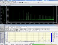
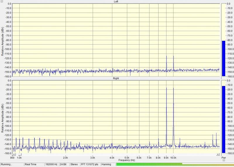
The THD value for the frequency of the first harmonic of 20K, of course, not so important. We can't hear the products of these distortions. Their frequencies are in the ultrasound. We compared the data of simulation and graphics from sound card to frequency 15K, look at the first image.
We were interested in intermodulation distortion are much more than harmonic distortion. The levels of these distortions for frequencies 18 and 21 is equal To -110 - -120 dB, see picture on the link.
diyAudio
We were interested in intermodulation distortion are much more than harmonic distortion. The levels of these distortions for frequencies 18 and 21 is equal To -110 - -120 dB, see picture on the link.
diyAudio
Attachments
The THD value for the frequency of the first harmonic of 20K, of course, not so important. We can't hear the products of these distortions. Their frequencies are in the ultrasound. We compared the data of simulation and graphics from sound card to frequency 15K, look at the first image.
We were interested in intermodulation distortion are much more than harmonic distortion. The levels of these distortions for frequencies 18 and 21 is equal To -110 - -120 dB, see picture on the link.
diyAudio
It is important to recognize that THD-20 is a metric for high-frequency nonlinearity, and whether one thinks that one can hear the harmonics is not relevant. I personally believe that what one hears is the IM products that result from high frequency nonlinearity. For example, I do like CCIF IM with 19+20kHz. That having been said, it does not invalidate THD-20 as a good measure of HF nonlinearity. It is very important, however, to realize that the relative amplitudes of the intermodulation products will usually be smaller, and often not numerically comparable to, the THD-20 percentages.
It is also important to bear in mind that the amount of distortion-reducing negative feedback available at the THD-20 harmonics is less than that at 20kHz, and decreases with increasing frequency. In contrast, the amount of NFB available at the odd-order intermodulation product frequencies of CCIF IM 19+20 is actually a tad more for the in-band products.
Cheers,
Bob
I told Excel to build a table...
Mark, following on kgrlee's suggestion to insert the R into the control transistor's emitter instead of its base, I'm interested to know whether there's a loose correlation between Cob, fT and hFE so that there can be a 'default' suggested value for Re that works well enough across the range of transistors normally used.
If you are happy to send me a copy your spreadsheet I'll enter the values and post the findings here.
Hopefully can fix any problems with the simple 2T CCS using a couple of $0.01 resistors and not resort to those expensive Vref ICs that you seem to love so much 😉
I would very much like to know how you measure under 1ppm THD20k at 150W 8R with a sound card. 😱
That is probably more interesting than your excellent designs. 🙂
But can you clarify please.
0.15ppm is 0.000015%, not 0.000,15%
Which is correct? Of course these are incredibly good figures whether 1.5ppm or 0.15ppm and the method to measure them will be excellent and worthy of further discussion.
I would also like to know measurement techniques.
THx-RNMarsh
But I would very much like to know which sound card you use to measure this ... especially at 20kHz.
The very best soundcards have effectively 20 bit resolution and for a good THD20k measurement, you would want at least 5x bandwidth ie 100kHz which implies 192kHz sampling is not quite good enough.
Is this how you obtained your 0.00015% THD20k measurement?
Our past member Dick Moore, RIP, used a notch filter as a distortion "magnifier" with a sound card
and a QuantAsylum QA-400:
https://web.archive.org/web/20150218013645/http://moorepage.net/Twin-T.html
You make a good point about 192 sampling, but you could observe 18 KHz or 10 to 18 and if
the 5th is low enough then, while not proof, come to the conclusion that the 5th is not needed at 20 KHz.
Really, you should use twin tone testing since if the amp has an output filter it will suppress harmonics,
or take the output reading before the filter.
Last edited:
I forgot to say that the comparison of data and simulation of the sound card a filter was applied to suppress the first harmonic of the signal. Therefore, the level of distortion and interference in reality to 20 dB lower than the picture.
Bob, I think I've suggested this to you before.It is important to recognize that THD-20 is a metric for high-frequency nonlinearity, and whether one thinks that one can hear the harmonics is not relevant. I personally believe that what one hears is the IM products that result from high frequency nonlinearity. For example, I do like CCIF IM with 19+20kHz. That having been said, it does not invalidate THD-20 as a good measure of HF nonlinearity. It is very important, however, to realize that the relative amplitudes of the intermodulation products will usually be smaller, and often not numerically comparable to, the THD-20 percentages.
It's to show the maths behind the 'equivalence' factor of each THD harmonic & the corresponding IMD measurement. Actually just the factor itself would be good
I did this in Jurassic times and wrote it all in my B&K 1902 manual in da days wen I kud reed en rite but my single remaining brain cell is no longer capable of even simple arithmetic so I can't easily replicate this.
You have to make all sorts of assumptions like constant feedback, zillion GHz bandwidth etc but I think this would still be useful.
T117, perhaps you could help Bob do this 🙂
______________
If you could post the circuits of such filters, this would let us mere mortals decide if this type of measurement is beyond us.I forgot to say that the comparison of data and simulation of the sound card a filter was applied to suppress the first harmonic of the signal. Therefore, the level of distortion and interference in reality to 20 dB lower than the picture.
What sort of spec does this type of filter need? Does it need 1ppzillion THD too? Do you have separate ones for 1kHz and 20kHz?
I'm not sure just using up to the 5th harmonic is sufficient for good THD20k.
Inevitably, at near 1ppm level, the residual is spiky with crossover. Including up to the 10th harmonic is OK.
Last edited:
- Home
- Amplifiers
- Solid State
- Bob Cordell's Power amplifier book