If you wind around an metal can electrolytic cap, the inductance will drop (from coupling to the shorted turn the can makes) but resistance will stay the same... so that's less effective if you're concerned with keeping series R lowest.
now that the topic is being discussed here, i think it is a good idea to put it in your book....
to be honest, i never followed Dan Meyer's coil suggestion, i installed them right at the speaker binding posts....
i used shrinkable tubing in some of my coils....
I like the idea of using heat shrink tubing, but I am also being mindful of Chris' point that it may hinder the ability of the coil to get rid of heat.
Of course, if the coil only has 20 mohm instead of 40, power dissipation will be halved. Moreover, in normal program conditions average power will be quite small on quality music that is not severely compressed.
Cheers,
Bob
Hi Bob,
For the home constructor, keeping things reasonable and simple makes some sense. Anyone can certainly use epoxy, heat shrink or any other means to make the coil an intrinsic cylinder or block. If this is really what you want to do (you in a general sense, not Bob), I would recommend thermally conductive epoxy with a bolt hole. I'm thinking of the folks who are building large power amplifiers. We mortals don't normally have to worry about the coil heating up.
Thinking back to servicing 450 to 1200 watt amplifiers, I don't recall seeing overheated coils in but a few cases. Figure the current was high enough to short an output stage, that's impressive. So I am of the opinion that the coil losses are more important than worrying about the coils buzzing or whining. Of course the most important thing is that the amplifier remains stable with the value that is picked.
-Chris
Yes, the popular GE Silicone in a tube we use around the house is exactly what I am talking about. Just run it in lines in four positions. My goal is to stabilize the coil and limit movement. Trying to go all the way to make the coil a solid seems to be overkill to me, and I don't believe we are talking about a huge problem anyway. There are many good audio brands that simply wind the coils with heavy wire and that's the way they go into the PCB.What kind of silicone are you talking about and how do you smooth it out over the coil?
For the home constructor, keeping things reasonable and simple makes some sense. Anyone can certainly use epoxy, heat shrink or any other means to make the coil an intrinsic cylinder or block. If this is really what you want to do (you in a general sense, not Bob), I would recommend thermally conductive epoxy with a bolt hole. I'm thinking of the folks who are building large power amplifiers. We mortals don't normally have to worry about the coil heating up.
Okay, now that just sounds like all kinds of fun. Make sure the fumes aren't hazardous.I understand that DIY coil dope can be made by dissolving ping pong balls in acetone.
That's exactly what I had in mind.We do not want to spread the coil out because that reduces the inductance. We want it to be close-wound with ideally no space between the windings.
Exactly right. I keep some around for this purpose.The coating that makes it magnet wire that you refer to is the enamel insulating layer (magnet wire is also called enameled wire).
I don't either, but if my wife ever caught me using her stove for this I'd be a dead man.I don't think that is the coating that acts to bond the wires together when baked.
Now there is what I am talking about. With damping the motion will be reduced, with epoxy it simply will not occur. But even just wound and not treated, I still can't see this being an issue. Maybe in those monster power amps (Carver might use impregnated coils - I have never looked at them closely) the temperature and motion may be important. However, a person good with math can figure out the exact forces at play at peak current levels. Maybe also give numbers for sane power levels too. That should really tell you how much of a problem this might be - or not.It is the fact that such singing is a symptom that electromechanical vibration is occurring in response to the signal current, which cannot be a good thing. How bad it is on the audio signal is the question.
Thinking back to servicing 450 to 1200 watt amplifiers, I don't recall seeing overheated coils in but a few cases. Figure the current was high enough to short an output stage, that's impressive. So I am of the opinion that the coil losses are more important than worrying about the coils buzzing or whining. Of course the most important thing is that the amplifier remains stable with the value that is picked.
-Chris
Bob, what are MOF resistors?3. 18T, #22 on 2 MOF 3W resistors, 2 layers, length = 0.25: 27 mohm
Just a note that some power resistors have ferrous leads so this might not be a good way to wind inductors.
__________________
First we need to understand what the Inductor is for.
Then what nasties it might introduce while doing its job.
Without answering these 2 questions, any discussion is just an exercise in w*nking.
The inductor is part of the output circuit that enables the amplifier to be unconditionally stable with load.
Those who feel this is unnecessary haven't done enough 'real life' trials with real speakers. In the previous Millenium, I would have claimed ALL Golden Pinnae would exhibit bursts of oscillation on part of the output waveform depending on load, thermal & signal history .. including some famous names who post regularly on this forum and disown their designs when this is pointed out to them. 😡
In my experience, it is impossible, both in theory as well as real life, to ensure unconditional stability with load unless you have a series inductor or are happy with very poor THD performance.
There's been some over-the-top discussion about parasitic oscillation but this palls into insignificance compared to the products of EVIL speaker designers 😱
I outline some of the tests you need to do in discrete-opamp-open-design-231.html#post3266142 though this is about an OPA rather than a PA. The additional important 'real life' test is to use a big old guitar speaker and test at various frequencies and levels including overload.
More here
tpc-vs-tmc-vs-pure-cherry.html
Nasties introduced by the inductor
The obvious one is that the inductance changes the frequency response depending on the EVIL loads us EVIL speaker designers inflict on amps.
But this is well researched and 2uH is sufficiently small to have no detectable effect. If anyone knows different, please post examples and measurements on real speakers.
Part of this is the DC resistance but in fact this is ALWAYS swamped by speaker cable as to be moot. But its so easy to get DC to tens of milliohms that there's no excuse not to do so.
The same goes for any parasitic capacitance. It has no practical effect on the stability and/or frequency response of the system.
The nastiest thing that the inductor can introduce is it might pick up fields from the nasty Class B currents running about in the amp. It is likely layout (especially of power supply leads) and positioning are the most important factors. Self goes into this but with a crosstalk emphasis IIRC
If you are really worried, a toroidal core is the best and is also one of the configurations that gives minimum resistance.
____________________
Practical Inductors
AndrewT's Wheeler coil is the simplest for least resistance. IIRC, there was a short JAES (1970's?) article on this. [*]
But as the coils are so small, Self's single layer coil might be as good bearing in mind the above points.
If you are worried about the turns moving, close wind the coil and just dip in epoxy. This is the most convenient way to banish this evil.
Has anyone done any work on a 1ppm THD20k amp that shows moving turns in a sensible close wound inductor degrade performance?
The Meyer/Dynaco inductors wound round capacitors are truly EVIL
[*] BTW, the Wheeler formula holds even if you use a core. The bobbin needs to be of the same aspect ratio as an air-cored coil for least resistance.
Last edited:
The bonding coating on the magnet wire is a thermoplastic material, It is clearly discussed on the MWS website. It can be baked or solvent bonded if desired.
Welcome to MWS Wire Industries
ps. kgrlee,
I thought you were off sailing somewhere or something, haven't seen you for awhile.
Welcome to MWS Wire Industries
ps. kgrlee,
I thought you were off sailing somewhere or something, haven't seen you for awhile.
I use a 0.5 to 1 uH in my designs.
I would concur fully with Richard and Bob that an output L provides spades of benefit.
Without it, to guarantee stability you need to really reduce the loop gain and set the ULGF very low - hence the higher distortion.
I would concur fully with Richard and Bob that an output L provides spades of benefit.
Without it, to guarantee stability you need to really reduce the loop gain and set the ULGF very low - hence the higher distortion.
Last edited:
So what is a legitimate reason not to include an output zobel or inductor, under what conditions would you want or need to leave that out?
I use two zobels, one that the terminals (after the coil) and one at the output PCB. Coil is wound over a 12W MRA non inductive resistor.
I use 2mm wire and I use 15 turns which gives me about 0,7 uH. I never had any issues with heat. For mechanical stability I coat the coil (and the resistor) with epoxy.
http://www.vishay.com/docs/31801/mra.pdf
I use 2mm wire and I use 15 turns which gives me about 0,7 uH. I never had any issues with heat. For mechanical stability I coat the coil (and the resistor) with epoxy.
http://www.vishay.com/docs/31801/mra.pdf
Bonsai,
I have a terrible link to your site so it is taking me forever to navigate to your post past the short paragraph about output inductors. I keep trying to find the main information past that little blurb. Thanks.
I have a terrible link to your site so it is taking me forever to navigate to your post past the short paragraph about output inductors. I keep trying to find the main information past that little blurb. Thanks.
Bonsai,
I have a terrible link to your site so it is taking me forever to navigate to your post past the short paragraph about output inductors. I keep trying to find the main information past that little blurb. Thanks.
Hope this works better
http://hifisonix.com/wordpress/wp-content/uploads/2014/11/Output-L_1.pdf
I use a 0.5 to 1 uH in my designs.
I would concur fully with Richard and Bob that an output L provides spades of benefit.
Without it, to guarantee stability you need to really reduce the loop gain and set the ULGF very low - hence the higher distortion.
Hi Bonsai,
I use smaller values than 2uH whenever I can, but the 2uH target we are talking about here is a reasonably conservative target that will keep most people out of trouble on most designs.
Agreed that most well-done designs with good layout can tolerate 1uH.
Of course, many of the issues we are discussing here are reduced with smaller inductance values.
I used 0.5uH in my MOSFET power amplifier.
Cheers,
Bob
Bob, what are MOF resistors?
Hi kgrlee,
MOF resistors are Metal Oxide Film resistors. I like to stay away from wirewound resistors, even the ones that are noninductive. MOFs are very non-inductive and available up to at least 5W ratings. I've mostly used the 3W versions, and if necessary put them in parallel to get higher wattage. They are flameproof and can tolerate extremely high brief overload.
Here is an example:
3W Metal Oxide Film resistor (MOF), 1 ohm, 5%
TE Connectivity 2-1625892-6,
DigiKey #A104951CT-ND, ROX, Neohm Series. 5.5 X 16mm.
31 cents in quantity of 10.
I have built some L-R networks with the coil wound on two of these side-by-side in series, each 1 ohm to achieve 2 ohms. On one end they are connected together, the other end forms a radial mounted component (they stand up). Two layers of wire are wound on them, starting at the bottom, going up and then back down
Cheers,
Bob
Interesting discussion. Coil design and theory is something I've never really studied in depth and so I would be interested to know a 'guestimate' of the value of these.
What is the diameter, length, number of turns and AWG?
Cheers,
Bob
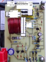
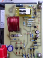
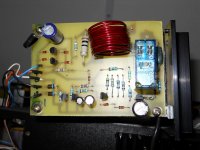
The inductace is set by the coil size ( diameter number of turn and lenght )
But if the coil is not glued or if it is loose at heavy current if may vibrate and will change value ... will this induce distotion I dont know .. but take no chance I use clear nail polish an glue the coil
But if the coil is not glued or if it is loose at heavy current if may vibrate and will change value ... will this induce distotion I dont know .. but take no chance I use clear nail polish an glue the coil
Attachments

For the one, about 3.12 uH (making some geometry assumptions).
Many thanks for that
 I'd say your estimations of size are definitely in the right ballpark... in fact I have the relays in front of me right now as a scale check. Brilliant, ta very much 🙂
 Mechanical relay in one image, solid state in the other because the pics were from 4yrs ago when I did the swap.
Up until very recently I'd always considered the output inductor as a very non critical part in the scheme of things. Perhaps these are a little on the large size value wise, based on current opinion. In fact I suspect for 99.9% of situations that the amp doesn't technically need them as it has a deliberately included 0.22 series output resistance. They were included for completeness as much as anything.
What is the diameter, length, number of turns and AWG?
Cheers,
Bob
Well its all neatly plumbed into its rack... so getting all that info would have been a major dismantling exercise, hence the guestimate bit 🙂 I don't even know the exact wire gauge tbh, just that it was fairly 'thick' and was some I had left over from building Dougs blameless back in the day.
- Home
- Amplifiers
- Solid State
- Bob Cordell's Power amplifier book