For all of the same reasons, open-loop bandwidth in these sorts of designs does not matter.
Cheers,
Bob
Do you think you'll ever convince John?
I'll move your question to Bobs thread.

I thought this is Bob's thread.
Where is Bob's thread? Can you link to it.
Do you think you'll ever convince John?
Do you mean like sticking a resistor on the VAS, loading it down, to stretch the DC gain out 1 GHz or something like that?
Good old John Curl has a nifty trick for driving open loop DC gain into the stratosphere: he cascodes the 2nd stage driver ("VAS") and also cascodes the 2nd stage constant current source load. {In fact it's more complicated but that's the executive summary}. This makes the 2nd stage DC gain truly enormous:
gain = gm * (driver_ro || ccs_ro || ops_zin)
Cascoding makes the driver_ro and the ccs_ro, gigantic. Then he applies a cute trick: he builds the output stage cascade of followers, using MOSFETs as the first of the followers. Their zin is ~ infinity. So the output stage's zin is ~ infinity and it does not load the 2nd stage (at DC) even one little bit. Result: 2nd stage gain is enormous. So the open loop DC gain of the amplifier as a whole, is also enormous. Cute.
Of course JC would object to my description of his design's purpose, he claims not to love huge open loop DC gain (== low open loop bandwidth). But that's how he builds his single stage folded cascode power amps: with gigantic DC gain in the "VAS" including circuit design decisions that, it so happens, boost DC gain enormously.
Last edited:
Good old John Curl has a nifty trick for driving open loop DC gain into the stratosphere: he cascodes the 2nd stage driver ("VAS") and also cascodes the 2nd stage constant current source load. {In fact it's more complicated but that's the executive summary}. This makes the 2nd stage DC gain truly enormous:
gain = gm * (driver_ro || ccs_ro || ops_zin)
Cascoding makes the driver_ro and the ccs_ro, gigantic. Then he applies a cute trick: he builds the output stage cascade of followers, using MOSFETs as the first of the followers. Their zin is ~ infinity. So the output stage's zin is ~ infinity and it does not load the 2nd stage (at DC) even one little bit. Result: 2nd stage gain is enormous. So the open loop DC gain of the amplifier as a whole, is also enormous. Cute.
Of course JC would object to my description of his design's purpose, he claims not to love huge open loop DC gain (== low open loop bandwidth). But that's how he builds his single stage folded cascode power amps: with gigantic DC gain in the "VAS" including circuit design decisions that, it so happens, boost DC gain enormously.
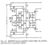
Cascoding helps a lot, and is a common approach used by many for many decades. Also, use of MOSFETs in the drivers our outputs increases it. Look at the circuit of my MOSFET power amplifier with error correction on my web site. It uses a cascoded push-pull VAS and has MOSFET output transistors, so its dc gain is also in the stratosphere.
However, folded cascodes generally have considerably less gain than a common-emitter type of VAS.
Cheers,
Bob
Good old John Curl has a nifty trick for driving open loop DC gain into the stratosphere: he cascodes the 2nd stage driver ("VAS") and also cascodes the 2nd stage constant current source load. {In fact it's more complicated but that's the executive summary}. This makes the 2nd stage DC gain truly enormous:
gain = gm * (driver_ro || ccs_ro || ops_zin)
Cascoding makes the driver_ro and the ccs_ro, gigantic. Then he applies a cute trick: he builds the output stage cascade of followers, using MOSFETs as the first of the followers. Their zin is ~ infinity. So the output stage's zin is ~ infinity and it does not load the 2nd stage (at DC) even one little bit. Result: 2nd stage gain is enormous. So the open loop DC gain of the amplifier as a whole, is also enormous. Cute.
Of course JC would object to my description of his design's purpose, he claims not to love huge open loop DC gain (== low open loop bandwidth). But that's how he builds his single stage folded cascode power amps: with gigantic DC gain in the "VAS" including circuit design decisions that, it so happens, boost DC gain enormously.
Okay. But isn't it the AC gain that matters?
But to me the essential difference is that Curl's power amp topology connects MOSFET gates to the "VAS" output node. These have infinite input impedance. So the 2nd stage gain is stratospheric.my MOSFET power amplifier with error correction on my web site. It uses a cascoded push-pull VAS and has MOSFET output transistors, so its dc gain is also in the stratosphere.
Your power amp connects Q20,Q21 emitter follower bases to the "VAS" output node. These have finite input impedance. So the 2nd stage gain is merely tropospheric. schematic below.
_
Attachments
What really counts is the open loop gain at frequencies above the intercept with the DC open-loop gain; like usually 1kHz and above. In other words, the open loop gain that matters is when it is being controlled by the compensation, such as the Miller capacitor, and is falling with frequency.
For all of the same reasons, open-loop bandwidth in these sorts of designs does not matter.
Cheers,
Bob
I am not sure what sort of design you are talking about, but some say that similar distortion (low enough) thought whole audio spectrum will sound better and that is possible to achieve with wide open-loop bandwidth(or loop gain). I don't have enough listening experience to say it's true and would like to know others opinion.
.edit
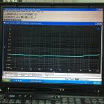
Richard showed that plot before in this thread.
BR Damir
Attachments
Last edited:
But to me the essential difference is that Curl's power amp topology connects MOSFET gates to the "VAS" output node. These have infinite input impedance. So the 2nd stage gain is stratospheric.
Your power amp connects Q20,Q21 emitter follower bases to the "VAS" output node. These have finite input impedance. So the 2nd stage gain is merely tropospheric. schematic below.
_
This is all fine about the mosfet's infinite Z on dc gain. but what about the capacitance loading on the VAS?
I am not sure what sort of design you are talking about, but some say that similar distortion (low enough) thought whole audio spectrum will sound better and that is possible to achieve with wide open-loop bandwidth(or loop gain). I don't have enough listening experience to say it's true and would like to know others opinion.
.edit
Richard showed that plot before in this thread.
BR Damir
Damir-- if I may take some editorial license, let me try to explain (I think you guys are making complementary points). Bob is talking dominant pole designs, so whether you have 140 db DC gain and 1 Hz OL bandwidth or 120 db DC gain and 10 Hz OL bandwidth, it doesn't really matter (as DC gain can vary quite a lot), and the compensation network, in full force by 1 kHz and the corresponding loop gain curve is much more important. Nothing to say one cannot make an exemplary high OL bandwidth design.
For Every Complex Problem, There Is an Answer That Is Clear, Simple, and Wrong
but there are some reasons involving music signal properties and human hearing that suggest we shouldn't want:
I see this again and again, keep trying to show that any weighting for human listening pleasure with music really shouldn't be expected to be that simple
of course what I really recommend on feedback theory, sim and measurement grounds is two-pole compensation over single dominant pole Miller
It is a standard result in feedback theory that global loop gain linearizes a feedback amplifier more effectively than any combination of local feedback around the same total gain blocks
with two-pole compensation you can expose 20 dB more global open loop gain by 20 kHz if your circuit has the gain, and I still see no reason to cap/shape the exact "open loop corner frequency", just let the open loop gain rise at lower frequencies to whatever level to let the excess loop gain do its negative feedback "magic"
but there are some reasons involving music signal properties and human hearing that suggest we shouldn't want:
and that...high OL bandwidth design
is very likely wrong...some say that similar distortion (low enough) thought whole audio spectrum will sound better and that is possible to achieve with wide open-loop bandwidth(or loop gain).
I see this again and again, keep trying to show that any weighting for human listening pleasure with music really shouldn't be expected to be that simple
...Originally Posted by Dave Zan View Post
...
I'm very surprised to hear this from serious students of audio amplification - commercial music audio signal, human perception and global feedback effect on errors by frequency component all make "flat feedback over audio bandwidth" a dubious prescriptionI don't think this is necessary, but it is sufficient.Originally Posted by BesPav View Post
we want to have constant feedback depth (and may be phase) all around audioband.
My view that once we have sufficient open loop gain to have the 20 kHz that we want then there is little point to add more from DC to 20 Khz.
...
David
several papers surveying "music" suggest a Power Bandwidth of only 3-5 kHz, rolling off above
common musical instruments, voice have fundamentals substantially below even 3 kHz
Human hearing Critical Bands are ~ log Frequency spaced, fewer above that 3-5 kHz music signal power bandwidth than below
Global Feedback reduces errors by the amount of excess loop gain at the Frequency of the error component
Global feedback reduces signal level in early stages (reducing their distortion products), again by the amount of feedback at the signal frequency – which can be the more important distortion reducing mechanism for 3rd order and above distortion – like the typical bjt diff pair tanh function that is “outside” the feedback loop
IMD difference components can be clearly audible with multitone tests like 1:1 19+20 kHz 1 kHz difference - and more feedback at 1 kHz does reduce the 1 kHz IMD component vs "flat feedback" by the factor of ~ 20 expected if a 1st order global feedback slope down to few hundred Hz is allowed
putting the above together suggests to me strongly weighting, allocating more distortion reducing feedback down to at least 3 kHz vs "flat below 20 kHz"
because Psychoacoustics such as Critical band density, noise floor suggest human hearing is far more sensitive to errors below 3-5 kHz than above
because there's substantially more music signal amplitude lower down than 20 kHz
because there's additional IMD error product frequencies that fold down to our more acute hearing range
and because it “costs” practically nothing in stability margin
of course what I really recommend on feedback theory, sim and measurement grounds is two-pole compensation over single dominant pole Miller
It is a standard result in feedback theory that global loop gain linearizes a feedback amplifier more effectively than any combination of local feedback around the same total gain blocks
with two-pole compensation you can expose 20 dB more global open loop gain by 20 kHz if your circuit has the gain, and I still see no reason to cap/shape the exact "open loop corner frequency", just let the open loop gain rise at lower frequencies to whatever level to let the excess loop gain do its negative feedback "magic"
Last edited:
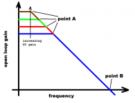
It adds to the miller-effect-multiplied compensation capacitor, the C which is connected from input to output of the 2nd stage. As others continue to point out, the shape of the open loop frequency response is simplicity itself: two straight lines. DC gain determines the corner at point "A" and (gm/Cc) determines the intercept at point "B". Simple.... but what about the capacitance loading on the VAS?
_
Attachments
Damir-- if I may take some editorial license, let me try to explain (I think you guys are making complementary points). Bob is talking dominant pole designs, so whether you have 140 db DC gain and 1 Hz OL bandwidth or 120 db DC gain and 10 Hz OL bandwidth, it doesn't really matter (as DC gain can vary quite a lot), and the compensation network, in full force by 1 kHz and the corresponding loop gain curve is much more important. Nothing to say one cannot make an exemplary high OL bandwidth design.
Daniel, thank you hop in. What I am trying to clear for myself is a bit different. Bob is talking dominant pole design and I try to include multipole design into discussion. If I can make open loop gain(or loop gain) flat from DC to about 20 or 30 kHz that will have as result flat distortion plot though out audio spectrum.
Does it sound better than then OL with very high DC gain and low OL bandwidth, but the same OL gain at 20 kHz?
.edit
I see jcx answer now, but I would like others opinion too.
Last edited:
Does it sound better than then OL with very high DC gain and low OL bandwidth, but the same OL gain at 20 kHz?
I haven't the foggiest idea. 🙂
I'd wager, without getting into the vagaries of the now-infamous opamp thread, that any differences between a bunch of very-low distortion designs (as yours is) would be very difficult to tell apart. Noise and high-power nonlinearities would be much more likely to differentiate, and I'm not anywhere near a good enough circuit designer to follow through overload behavior in different circuits.
I thought this is Bob's thread.
Where is Bob's thread? Can you link to it.
This is Bobs thread. Spassig's question was elsewhere... but now it is here 🙂
It adds to the miller-effect-multiplied compensation capacitor, the C which is connected from input to output of the 2nd stage. As others continue to point out, the shape of the open loop frequency response is simplicity itself: two straight lines. DC gain determines the corner at point "A" and (gm/Cc) determines the intercept at point "B". Simple.
_
Right. So there isn't much point in shoving the dc gain up further. The slope stays the same.
Mosfet C is non linear. So we would want to use that for the miller C.
we can enjoy even 5 kHz bandlimited AM Radio music
we can follow lyrics, melodies, harmonies, tease out individual instruments
now try a frequency translation of the same 5 kHz BW music to the 15-20 kHz band - what do you expect to hear now?
doesn't that argue that any “flat distortion profile” prescription over 20 Hz - 20 kHz is ignoring human hearing and music signal properties as I went into in my post above?
But that's how he builds his single stage folded cascode power amps: with gigantic DC gain in the "VAS" including circuit design decisions that, it so happens, boost DC gain enormously.
You can give virtually any amplifier infinite and even negative open-loop gain with a very small amount of positive feedback to the input offset voltage. I have demoed this with scope photo here years ago. The DC input region for full output is at most 10's of uV and virtually a straight line, anyone who ever used the old Tek op-amp curve tracer would know this, op-amps with thermal problems like gull wing shapes disappeared as soon as the problem was demonstrated circa 1974.
I even demonstrated this with the Otala amp in simulation.
Then he applies a cute trick: he builds the output stage cascade of followers, using MOSFETs as the first of the followers. Their zin is ~ infinity. So the output stage's zin is ~ infinity and it does not load the 2nd stage (at DC) even one little bit.
Yes, and also much more nonlinear, since the mosfet input impedance is very nonlinear, pretty much Crss capacitive, much worse than a low Cob bipolar. Take a look at how the Crss varies with the Vds voltage in a typical high voltage low power mosfet like the 2SK4150 https://www.renesas.com/en-us/doc/products/transistor/004/rej03g1909_2sk4150ds.pdf it's between about 80pF @1V and 3pF @25V. For the same voltage span, a 2SC3503 has Cob varying from 6pF to 2 pF.
The "cute" trick for using a mosfet in the VAS, while certainly providing a large (open) loop gain, goes in fact straight against the "open loop linearity" design philosophy, and it was long time proven to be a false solution to a real problem (the VAS nonlinearity).
- Home
- Amplifiers
- Solid State
- Bob Cordell's Power amplifier book