Presumably you have references to the work that shows this behaviour.Yes, just the magnitude of the speaker system's input impedance doesn't show this. For a non-periodic input voltage,
the peak transient input current can be much higher than that for a periodic input, for the same peak input voltage.
The input current as a function of time can be calculated for a specific non-periodic input waveform with
the crossover's transfer function.
I really want to see them as I have done a LOT of work on the subject.
If you are quoting Otala instead of real life and believe what he claims about amps or speakers, you can just ignore everything I say. 😱
I also think you should brush up on periodic vs non-periodic current into various loads. But I'm prepared to be proven wrong so please show us the maths that demonstrates your assertion.
Jan, I have not found any difference with or w/o xovers for this unicorn 🙂
I also think you should brush up on periodic vs non-periodic current into various loads.
But I'm prepared to be proven wrong so please show us the maths that demonstrates your assertion.
Remember that impedance (as in a speaker system's input impedance) is only defined and measured as a steady state quantity.
The instantaneous value of current for a non-periodic input voltage must be found by more general methods.
This is basic circuit theory. There have been related papers, perhaps I or someone else here can look up one for you.
Last edited:
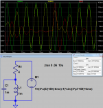
just plopped down some parts in sim - not arguing that they are "real" but you can see the principle
green is a sine at the resonant freq, reverses phase on the 5th cycle
can see the LC node yellow V pump up
the red trace peaks (negative) at ~210 mA on the 1st cycle, at the reverse we see 410 mA peak ~= 1.7x the calculated resistive current and ~2x the starting peak
for more fun change the 5 cycles to 5.25 cycles - 495 mA peak!
Attachments
Last edited:
I don't understand why. I read many times in your book......AND more importantly to stress, I totally agree with what you said in p100 to p103 and p186 to p188. That if you make Re=r'e at idle, then at idle, Zout= (Re+r'e)/2=Re. Then at high current where one side is off and r'e of the other side r'e<< Re, the output impedance is still Re. There will be no gm doubling.I think you still get gm doubling when the current sourced to the load exceeds 2A.
Cheers,
Bob
This means that the output impedance equals the Re at any current level whether it is at idle or above 2A. I understand right at the stage goes from Class A to Class B, r'e still comes into play and the output impedance is still a little higher than Re. That's where you still have distortion even in Oliver's condition.
gm doubling is caused by output impedance rise at large signal amplitude. But there is no reason why output impedance will rise above Re when the transistor conduct over 2A.
Can you explain if there are more to it than what I described above.
Thanks
Last edited:
just plopped down some parts in sim - not arguing that they are "real" but you can see the principle
green is a sine at the resonant freq, reverses phase on the 5th cycle
can see the LC node yellow V pump up
the red trace peaks (negative) at ~210 mA on the 1st cycle, at the reverse we see 410 mA peak ~= 1.7x the calculated resistive current and ~2x the starting peak
for more fun change the 5 cycles to 5.25 cycles - 495 mA peak!
This will never be a real world scenario, as L and R will be fused into one, what you have mad is an un-damped resonance circuit, off course it has peaks
Last edited:
just plopped down some parts in sim - not arguing that they are "real" but you can see the principle
green is a sine at the resonant freq, reverses phase on the 5th cycle
can see the LC node yellow V pump up
the red trace peaks (negative) at ~210 mA on the 1st cycle, at the reverse we see 410 mA peak ~= 1.7x the calculated resistive current and ~2x the starting peak
for more fun change the 5 cycles to 5.25 cycles - 495 mA peak!
This is of course still predicted by it's impedance, just not the same way you would calculate for a resistor.
I don't see a way that the surge current can exceed the total rail voltage divided by the coil resistance.So a +-25V amp into 4R would have max 12.5A max. Anything wrong with this?
This will never be a real world scenario, as L and R will be fused into one, what you have mad is an un-damped resonance circuit, off course it has peaks
That's nice and rational, but the total rail voltage rule seems to be foolproof. Since the level of damping of speaker impedance curves is highly variable, can we reasonably loosen the rule without losing foolproof status?
Let's say the coil resistance is 6R, and the impedance rises to 25R at Fo, and the amp has +-25V rails. This means at the worst point we have a divider of 6R over 19R. This means the max fault voltage is 50V*(19R/25R)=38V. 38V is only 24% less surge voltage. That's 6.3A rather than 8.3A.
If you conform to Olivers condition, your amplifier is now the distortion profile shown by the 'B' plot. You can't win.And if I conform to Oliver's condition, there will be NO gm doubling and the distortion is not going to be as high as your graph.
Presumably you have references to the work that shows this behaviour.
I really want to see them as I have done a LOT of work on the subject.
If you are quoting Otala instead of real life and believe what he claims about amps or speakers, you can just ignore everything I say. 😱
I also think you should brush up on periodic vs non-periodic current into various loads. But I'm prepared to be proven wrong so please show us the maths that demonstrates your assertion.
Jan, I have not found any difference with or w/o xovers for this unicorn 🙂
Hmmm. I remember his article with measurements on the Yahama NS1000 wasn't it? Anyway, this should yield to a simulation of a representative crossover.
Edit - just now saw jcx's post http://www.diyaudio.com/forums/soli...lls-power-amplifier-book-583.html#post4387276
Jan
Last edited:
An amplifier puts out a voltage sving, the speaker the asks for currents according to it's Z at a given frequency. Speakers have resonances, common for these is that the speaker have higher impedance at the resonances, and thus demands less currents. The cravet is that there's a delay or a phase shift associated with the resonances, this muddies the picture somehow and makes the work environment of the amplifier uncertain. To my knowledge not a lot work has been done to analyse this interaction. Quite sure that this an area where there's grounds for a big separation in performance of different amplifier topologies.
As a speaker designer I try to target the speaker resonances quite vigorously. I have abandoned the traditional closed and vented textbook designs completely. I my book they were not developed to enhance fidelity,they were merely created to enhance the possible frequency range of a given driver/cabinet komination. Like driveing a car with just springs and no suspension. Surely the ride gets bumpy. Closed cabinets makes high level sines into triangles. this is the nature of sping induced forces on motion.
As a speaker designer I try to target the speaker resonances quite vigorously. I have abandoned the traditional closed and vented textbook designs completely. I my book they were not developed to enhance fidelity,they were merely created to enhance the possible frequency range of a given driver/cabinet komination. Like driveing a car with just springs and no suspension. Surely the ride gets bumpy. Closed cabinets makes high level sines into triangles. this is the nature of sping induced forces on motion.
Last edited:
Not really. The amplifier just sources or sinks current so that the output voltage follows the input (times some multiplier). The output current being out of phase with the output voltage isn't a big problem. It will change the distortion profile of the amplifier slightly (compared to in-phase), but nothing drastically for the worst.An amplifier puts out a voltage sving, the speaker the asks for currents according to it's Z at a given frequency. Speakers have resonances, common for these is that the speaker have higher impedance at the resonances, and thus demands less currents. The cravet is that there's a delay or a phase shift associated with the resonances, this muddies the picture somehow and makes the work environment of the amplifier uncertain.
An amplifier puts out a voltage sving, the speaker the asks for currents according to it's Z at a given frequency. Speakers have resonances, common for these is that the speaker have higher impedance at the resonances, and thus demands less currents. The cravet is that there's a delay or a phase shift associated with the resonances, this muddies the picture somehow and makes the work environment of the amplifier uncertain. To my knowledge not a lot work has been done to analyse this interaction. Quite sure that this an area where there's grounds for a big separation in performance of different amplifier topologies.
Matti Otala has done several articles on the amplifier-speaker interface and iirc even coined the term iim (interface intermodulation); he was pretty good in coming up with catchy terms, Matti was ;-)
Also Jean Hiraga has done work on it. Should all be available on the 'net.
Edit: see here: http://linearaudio.nl/sites/linearaudio.net/files/otala interface intermoduation ww 11-80 12-80.pdf
Jan
Last edited:
Thanks for this jcx.just plopped down some parts in sim - not arguing that they are "real" but you can see the principle
green is a sine at the resonant freq, reverses phase on the 5th cycle
can see the LC node yellow V pump up
the red trace peaks (negative) at ~210 mA on the 1st cycle, at the reverse we see 410 mA peak ~= 1.7x the calculated resistive current and ~2x the starting peak
for more fun change the 5 cycles to 5.25 cycles - 495 mA peak!
For even more fun, have a look at Otala's papers on the subject .. bits of which I believe are in Bob & Doug's books. Even funkier waveforms and higher peak currents.
Now will someone dig up a music waveform (even modern 'music' !!??) that even approximates to this and triggers this behaviour?
_____________________
rayma, I'm very aware of the difference between instantaneous and average current. Indeed I took a lot of trouble to be able to monitor instantaneous currents demanded by speakers in my experiments on this subject.
You might also like to throw in the fact that speakers, including their impedance, are NOT linear time-invariant. It's just convenient for us to assume this .. eg to determine the maximum current required in non-fault conditions.
I have yet to fault this particular use of the assumed linear time invariant impedance curve.
In fault conditions, the priorities change .. and my instantaneous current monitor shows what happens.
This is how I can say I know of only one real life case where the (instantaneous 😀 ) current demanded exceeds that calculated from the impedance curve. I've looked for and observed this in real life.
If anyone else has seen the other species of this unicorn in the flesh, or even a paper that purports to have seen it .. rather than theorize it can happen .. please speak up.
___________________
BTW, please don't think I'm dissing these claims. I'm REALLY interested in EVIDENCE that this happens. I'm just trying to dig up FACTS rather than supposition and half baked theories.
At the same AES conference, one of Otala's students did an excellent paper which proved that the professor's zillion V/us slews NEVER occur. 😱
Last edited:
At the same AES conference, one of Otala's students did an excellent paper which proved that the professor's zillion V/us slews NEVER occur. 😱
Do you remember which convention or paper #?
jan
I'm afraid I don't remember the young man's name or that of his paper.Do you remember which convention or paper #?
It was AES Hamburg, 1981
If I may beg a morsel in return ... I believe you were involved in DBLTs on bandwidth limitation this Millenium.
Can you point us to more details?
Done...I think the XD-PP circuit would work better and be less dependent on load reasistance and phase angle if the pull-down current source were made dependent on output current. Output current can be measured with a very small resistor in series with the return leg of the loudspeaker....
Good point. Often overlooked.In many cases that precious 26mV or so is not maintained at all times during dynamic program material.
Technics SE-A1I think it might have been Pioneer who used this scheme on one of their amplifiers back in the 70's....
If you conform to Olivers condition, your amplifier is now the distortion profile shown by the 'B' plot. You can't win.
You can have high idle current and still satisfy Oliver's condition. As I kept giving example of 1A bias current, I get 2A of class A current vs only 1A of class A in XD. I would get 8W of Class A vs XD only have 2W before hitting the kink of the graph and distortion goes up.
With the 1A bias, the kink move up to double the voltage of the XD that has 1A. the higher voltage the kink goes up to, the less distortion it is.
This is not the B in Self's plot.
Leach's Double Barreled does this.....................You'd probably be better with a class A amplifier with sliding power supplies. The class A amplifier power supplies are provided by a couple of class B amplifiers, driven by copies of the input signal. The power rails of the class A amplifier can therefore dynamically adjust to only a few volts above the output level, dissipation would be acceptable................. An interesting concept, nonetheless.
The cascode swings the voltage fed to the output devices (and drivers)
- Home
- Amplifiers
- Solid State
- Bob Cordell's Power amplifier book