I agree with Rodolfo. 🙂
Ovidiu wrote:
Whether that matters to you or not depends on what your design goals are. As your performance goals, stated on your website, are focussed on THD and IMD then you may reasonably decide that complexity is not a concern.
You may have noticed that I choose not to give direct design advice in this forum, except for basic design help. I do try to expose myths and subjective claims that cannot be substatiated objectively. Otherwise, I choose to pose questions and make oblique comments that are intended to cause people to think differently about the problem.
In my experience, being able to correlate circuit attributes with sound quality is the crux of the matter. I have spent a great deal of time doing just this and it has led me to rethink the way I have applied engineering methods to audio design. I wince whenever the term "psychoacoustic" comes up because although this aspect is relevent in a way it is too often used as an excuse to discount the primacy of critical listening in the design process.
My advice to you is listen critically and humbly to your design and if it is not "the Ultimate Amplifier" yet then figure out what performance specifications are missing from your list. I have given some hints in this thread.

Brian
Ovidiu wrote:
The only comment I have directed at "The Ultimate Audio Amp" so far has been that it is "the most complicated amplifier design I have ever seen."If there are any shortcomings in our design or implementation, we would love to hear about.
Whether that matters to you or not depends on what your design goals are. As your performance goals, stated on your website, are focussed on THD and IMD then you may reasonably decide that complexity is not a concern.
You may have noticed that I choose not to give direct design advice in this forum, except for basic design help. I do try to expose myths and subjective claims that cannot be substatiated objectively. Otherwise, I choose to pose questions and make oblique comments that are intended to cause people to think differently about the problem.
In my experience, being able to correlate circuit attributes with sound quality is the crux of the matter. I have spent a great deal of time doing just this and it has led me to rethink the way I have applied engineering methods to audio design. I wince whenever the term "psychoacoustic" comes up because although this aspect is relevent in a way it is too often used as an excuse to discount the primacy of critical listening in the design process.
My advice to you is listen critically and humbly to your design and if it is not "the Ultimate Amplifier" yet then figure out what performance specifications are missing from your list. I have given some hints in this thread.
It is all one big bowl of soup as far as I can tell.Thanks again for your input. BTW, we are not in the right industry, we are on the right DIY forum.
Brian
traderbam said:Pretty good if you have shares in Toshiba.
And also this one, Brian!
Hi Brian,
You wrote:
This looks rather pompous, even tendentious, and I would question if, in this forum, this approach is either required or useful. People are in the forum of their own free will, and should be allowed to figure out for themselves, and by inferring from the consensus, if someone is blowing smoke up their !@#$. You are not a thought policeman, and you should not place yourselves above others, particularly when people are prepared to step forward, like Edmond and Syn08, and offer more than enough information for DIYers to build their own exceptional amplifier for private use.
Nobody here really knows who you are, you have no designs here, nor any credibility with commercial designs like say Alex Nikitin with Creek (who also shares his ideas freely). While there is no doubt you are very smart, you are using your abilities as a weapon, unpleasantly, and I speak not just from personal experience.
You may see it very differently, but I see your behaviour as superior, judgmental, and sometimes rude.
This would be fine if 'thinking differently' were always positive, but I fear it is not, and people are antagonised. No need for that. If people can take things the wrong way in a forum, they usually will. It is the nature of the medium.
Incidentally, you should not shy away from the word 'psychoacoustic'. It merely reflects the fact there are issues at the interface between ear and brain which colour perception, and if you are in the business of building music machines, you'd better examine it in some detail. At these levels of performance, audio goes way beyond Fletcher Munson, and you will find all sorts of tricks in commercial gear which exploit this, much of it buried deep in the codecs of audio compression.
Your wide experience might address Edmond's statement that he had deliberately cut out cascodes to trim component count as he found they had little benefit, or words to that effect. This is something of an audio heresy, caused me to smile!! I too have found cascodes of dubious benefit........ I wonder why this is so?
For myself, I will admit I do not contribute technically, as I make my living in this field and must be circumspect. In this sense I'm little different to you, but I always try to be nice.
Cheers,
Hugh
You wrote:
You may have noticed that I choose not to give direct design advice in this forum, except for basic design help. I do try to expose myths and subjective claims that cannot be substantiated objectively.
This looks rather pompous, even tendentious, and I would question if, in this forum, this approach is either required or useful. People are in the forum of their own free will, and should be allowed to figure out for themselves, and by inferring from the consensus, if someone is blowing smoke up their !@#$. You are not a thought policeman, and you should not place yourselves above others, particularly when people are prepared to step forward, like Edmond and Syn08, and offer more than enough information for DIYers to build their own exceptional amplifier for private use.
Nobody here really knows who you are, you have no designs here, nor any credibility with commercial designs like say Alex Nikitin with Creek (who also shares his ideas freely). While there is no doubt you are very smart, you are using your abilities as a weapon, unpleasantly, and I speak not just from personal experience.
You may see it very differently, but I see your behaviour as superior, judgmental, and sometimes rude.
Otherwise, I choose to pose questions and make oblique comments that are intended to cause people to think differently about the problem
This would be fine if 'thinking differently' were always positive, but I fear it is not, and people are antagonised. No need for that. If people can take things the wrong way in a forum, they usually will. It is the nature of the medium.
Incidentally, you should not shy away from the word 'psychoacoustic'. It merely reflects the fact there are issues at the interface between ear and brain which colour perception, and if you are in the business of building music machines, you'd better examine it in some detail. At these levels of performance, audio goes way beyond Fletcher Munson, and you will find all sorts of tricks in commercial gear which exploit this, much of it buried deep in the codecs of audio compression.
Your wide experience might address Edmond's statement that he had deliberately cut out cascodes to trim component count as he found they had little benefit, or words to that effect. This is something of an audio heresy, caused me to smile!! I too have found cascodes of dubious benefit........ I wonder why this is so?
For myself, I will admit I do not contribute technically, as I make my living in this field and must be circumspect. In this sense I'm little different to you, but I always try to be nice.
Cheers,
Hugh
Hugh, I have reported your last thread because I don't think this is the appropriate place for personal abuse. If you don't like my modus operandi then kindly ignore it.
We appreciate the fact that knowledgeable people prevent us from falling into pseudoscience traps and false claims just as we embrace those who warn us for egos and attitude.
What a great forum. 🙂
/Hugo
What a great forum. 🙂
/Hugo
BC amp distortion
Bob,
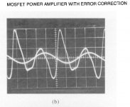
Could I ask you whether these estimates seem reasonable? I took your scope photo of the distortion residual and FFT'd it to get some idea of the relative sizes of H2, H3 and H4. I estimated H2=-43dB, H3=-55dB and H4=-60dB, or approx -40dB total.
Again, this is just a crude estimate. When 33dB of EC feedback is applied at 20kHz, estimating the knee shape of the 6dB roll-off from Spice, the reduced distortion figure is -70dB. Then if I apply 40dB of feedback at 20kHz, with perfect 6dB/oct roll-off, the total distortion is -104dB. Your actual measurement for the whole amp.
Given that the input/VAS must have added some distortion your original measurement of the -64dB THD of the EC must have been exaggerated.
If I assume 40dB EC fb at 20kHz the OS THD becomes -77dB and the whole amp -111dB. This would make the input stage distortion in the region of -109dB to give you -104dB overall.
Again, this is very crude but may help to give an idea of the relative contributions. If you wanted to turbo-charge your 1984 circuit and get it to deliver -120dB overall I anticipate more distortion reduction will be needed in the front end than the OS, and to achieve this with the same overall stability margin will be a worthy challenge.
Brian
Bob,
Could I ask you whether these estimates seem reasonable? I took your scope photo of the distortion residual and FFT'd it to get some idea of the relative sizes of H2, H3 and H4. I estimated H2=-43dB, H3=-55dB and H4=-60dB, or approx -40dB total.
Again, this is just a crude estimate. When 33dB of EC feedback is applied at 20kHz, estimating the knee shape of the 6dB roll-off from Spice, the reduced distortion figure is -70dB. Then if I apply 40dB of feedback at 20kHz, with perfect 6dB/oct roll-off, the total distortion is -104dB. Your actual measurement for the whole amp.
Given that the input/VAS must have added some distortion your original measurement of the -64dB THD of the EC must have been exaggerated.
If I assume 40dB EC fb at 20kHz the OS THD becomes -77dB and the whole amp -111dB. This would make the input stage distortion in the region of -109dB to give you -104dB overall.
Again, this is very crude but may help to give an idea of the relative contributions. If you wanted to turbo-charge your 1984 circuit and get it to deliver -120dB overall I anticipate more distortion reduction will be needed in the front end than the OS, and to achieve this with the same overall stability margin will be a worthy challenge.
Brian
Attachments
Re: BC amp distortion
Hi Brian,
I'm impressed by your reasoning skills here. These are the kind of thought experiments I like to do. I agree with your conclusions. I would not have thought of doing an FFT on the scope photo; cool! The downward progression of harmonics with frequency you mention is very nice information, and very encouraging.
I have indeed done some experiments in the past, and the input/VAS needs to be improved to reach the next level. As you pointed out in another post, just using newer transistors will get some improvement. I have also experimented with driving the JFET input stage cascodes with the appropriate common mode signal, and that has helped. I have also experimented with slightly more complex VAS circuits using error-corrected cascodes and error-corrected differential pairs, and that has helped. I did some of these experiments about a year ago, but got derailed, so I don't yet have a completed design to show for it. I don't think I will need to abandon the basic unipolar input stage architecture that I like, however.
There are also some changes that I need to make in the EC circuit to improve it as well.
Anyway, thanks, and I agree with your SWAGs here.
Cheers,
Bob
traderbam said:Bob,
Could I ask you whether these estimates seem reasonable? I took your scope photo of the distortion residual and FFT'd it to get some idea of the relative sizes of H2, H3 and H4. I estimated H2=-43dB, H3=-55dB and H4=-60dB, or approx -40dB total.
Again, this is just a crude estimate. When 33dB of EC feedback is applied at 20kHz, estimating the knee shape of the 6dB roll-off from Spice, the reduced distortion figure is -70dB. Then if I apply 40dB of feedback at 20kHz, with perfect 6dB/oct roll-off, the total distortion is -104dB. Your actual measurement for the whole amp.
Given that the input/VAS must have added some distortion your original measurement of the -64dB THD of the EC must have been exaggerated.
If I assume 40dB EC fb at 20kHz the OS THD becomes -77dB and the whole amp -111dB. This would make the input stage distortion in the region of -109dB to give you -104dB overall.
Again, this is very crude but may help to give an idea of the relative contributions. If you wanted to turbo-charge your 1984 circuit and get it to deliver -120dB overall I anticipate more distortion reduction will be needed in the front end than the OS, and to achieve this with the same overall stability margin will be a worthy challenge.
Brian
Hi Brian,
I'm impressed by your reasoning skills here. These are the kind of thought experiments I like to do. I agree with your conclusions. I would not have thought of doing an FFT on the scope photo; cool! The downward progression of harmonics with frequency you mention is very nice information, and very encouraging.
I have indeed done some experiments in the past, and the input/VAS needs to be improved to reach the next level. As you pointed out in another post, just using newer transistors will get some improvement. I have also experimented with driving the JFET input stage cascodes with the appropriate common mode signal, and that has helped. I have also experimented with slightly more complex VAS circuits using error-corrected cascodes and error-corrected differential pairs, and that has helped. I did some of these experiments about a year ago, but got derailed, so I don't yet have a completed design to show for it. I don't think I will need to abandon the basic unipolar input stage architecture that I like, however.
There are also some changes that I need to make in the EC circuit to improve it as well.
Anyway, thanks, and I agree with your SWAGs here.
Cheers,
Bob
Bob,
I think your 23 year old circuit topology has a lot of mileage left in it to exploit. I'm glad that analysis is credible...it was tricky.
Regarding your EC OS, I think you have cause for joy because I reckon you ought to be able to get the raw THD down below -50dB with modern, carefully chosen transistors and a little cunning. Your original circuit has high H2 and this ought to be relatively easy to tidy up. I would be hoping to get <-80dB closed loop with the same stability margin.
I haven't studied your front end circuit yet. But I agree with you about single-ended inputs...I'd keep it that way if you can. Sometimes mirroring pleases the eye more than it pleases the electrons 😉
Brian
traderbam said:Bob,
I think your 23 year old circuit topology has a lot of mileage left in it to exploit. I'm glad that analysis is credible...it was tricky.
Regarding your EC OS, I think you have cause for joy because I reckon you ought to be able to get the raw THD down below -50dB with modern, carefully chosen transistors and a little cunning. Your original circuit has high H2 and this ought to be relatively easy to tidy up. I would be hoping to get <-80dB closed loop with the same stability margin.
I haven't studied your front end circuit yet. But I agree with you about single-ended inputs...I'd keep it that way if you can. Sometimes mirroring pleases the eye more than it pleases the electrons 😉
Brian
Thanks, Brian. I agree. I do have a number of improvements planned for the EC stage, and have tried some before. Faster transistors and a topology that allows the use of lower voltage, fast transistors in the signal path is part of it. I'm also considering using a CFP for the error-differencing transistors to get better linearity and higher current gain. Overall, more attention to detail.
Cheers,
Bob
Bob Cordell said:..... I do have a number of improvements planned for the EC stage, and have tried some before. Faster transistors and a topology that allows the use of lower voltage, fast transistors in the signal path is part of it. I'm also considering using a CFP for the error-differencing transistors to get better linearity and higher current gain. Overall, more attention to detail.
Cheers, Bob
Hi Bob.
I doubt if it is worth the effort, as I have simulated a virtual amp, containing the following components:
1. Ideal front end.
2. Ideal EC circuit.
3. Real OPS with the best drivers and vert. MOSFETs you can get.
The unity gain frequency of the global FB loop and EC FB loop are both set at 2MHz. A higher Fc will seriously compromise the stability margin.
Idle current: 150mA, output power: 50W into 8 Ohm.
Results: THD20 = 4.2ppm (BW=200kHz), mainly consisting of odd harmonics, (which indicates a good matching of the complementary pairs btw). Maximum capacitive load = 16nF.
These results clearly demonstrate that in order to beat the 1ppm barrier a more rigorous approach is required than just paying "more attention to detail".
I'm afraid you have no other choice than adding a NDFL stage or combining TMC with EC (or both). 😀
Cheers, Edmond.
traderbam said:Bob,
..............
I haven't studied your front end circuit yet. But I agree with you about single-ended inputs...I'd keep it that way if you can. Sometimes mirroring pleases the eye more than it pleases the electrons 😉
............
Brian
Don't worry. We ordered not only the trannies from Toshiba but also one ounce of audio grade complementary electrons. They feel quite happy while pushing the slew rate to a maximum of 500V/us. 😛
Edmond Stuart said:
Hi Bob.
I doubt if it is worth the effort, as I have simulated a virtual amp, containing the following components:
1. Ideal front end.
2. Ideal EC circuit.
3. Real OPS with the best drivers and vert. MOSFETs you can get.
The unity gain frequency of the global FB loop and EC FB loop are both set at 2MHz. A higher Fc will seriously compromise the stability margin.
Idle current: 150mA, output power: 50W into 8 Ohm.
Results: THD20 = 4.2ppm (BW=200kHz), mainly consisting of odd harmonics, (which indicates a good matching of the complementary pairs btw). Maximum capacitive load = 16nF.
These results clearly demonstrate that in order to beat the 1ppm barrier a more rigorous approach is required than just paying "more attention to detail".
I'm afraid you have no other choice than adding a NDFL stage or combining TMC with EC (or both). 😀
Cheers, Edmond.
Hi Edmond,
We'll see. It sounds like we have a challenge here 🙂.
Indeed, I have not ruled out TMC, but I am not yet certain I need it to get there.
First of all, it depends a little on how we set the goal. If I set the goal as 100W into 8 ohms being 1 ppm THD-20 in a 80 kHz BW, I can almost certainly make it, I think. However, you would, perhaps rightly, say that was cheating, since your result is into 4 ohms.
My existing 6 ppm into 8 ohms, to the extent that it is dominated by the output stage, will drop down to 2 ppm or less just by adding the two additional output pairs to the output stage and the consequent increase in bias to 450 mA that you have.
I do agree that I have no plans at all to increase the closed-loop bandwidth to beyond 2 MHz.
I would further add that a perhaps better goal would be to have all distortion components of the CCIF twin tone 19+20 kHz test be below -120 dB at near full power into 4 ohms.
Your fine design has indeed inspired me to try a little harder 🙂.
Cheers,
Bob
Bob Cordell said:Hi Edmond,
We'll see. It sounds like we have a challenge here 🙂.
Indeed, I have not ruled out TMC, but I am not yet certain I need it to get there.
First of all, it depends a little on how we set the goal. If I set the goal as 100W into 8 ohms being 1 ppm THD-20 in a 80 kHz BW, I can almost certainly make it, I think. However, you would, perhaps rightly, say that was cheating, since your result is into 4 ohms.
My existing 6 ppm into 8 ohms, to the extent that it is dominated by the output stage, will drop down to 2 ppm or less just by adding the two additional output pairs to the output stage and the consequent increase in bias to 450 mA that you have.
I do agree that I have no plans at all to increase the closed-loop bandwidth to beyond 2 MHz.
I would further add that a perhaps better goal would be to have all distortion components of the CCIF twin tone 19+20 kHz test be below -120 dB at near full power into 4 ohms.
Your fine design has indeed inspired me to try a little harder 🙂.
Cheers,
Bob
Hi Bob,
Challenge? Perhaps you feel challenged. 🙂
Regarding figures, indeed, it depends on how we set the goal. To avoid any confusion, my figures above refer to a single pair OPS, just as in you original design and 4.2ppm is the absolute bottom limit. At 80kHz BW, it is 2.73ppm.
To make a fair comparison, I've added to more pairs and decreased RL to 4 Ohm. Now THD20=1.7ppm at 200W into 4 Ohm (BW=80kHz)
So it seems almost impossible to hit the 1ppm target without more drastic means. Besides, in real life, the front end will also add some distortion.
Regarding the CCIF twin tone test, I agree with you, this one is very important, although not replacement for a THD test of course.
Cheers, Edmond.
Edmond Stuart said:
Hi Bob,
Challenge? Perhaps you feel challenged. 🙂
Regarding figures, indeed, it depends on how we set the goal. To avoid any confusion, my figures above refer to a single pair OPS, just as in you original design and 4.2ppm is the absolute bottom limit. At 80kHz BW, it is 2.73ppm.
To make a fair comparison, I've added to more pairs and decreased RL to 4 Ohm. Now THD20=1.7ppm at 200W into 4 Ohm (BW=80kHz)
So it seems almost impossible to hit the 1ppm target without more drastic means. Besides, in real life, the front end will also add some distortion.
Regarding the CCIF twin tone test, I agree with you, this one is very important, although not replacement for a THD test of course.
Cheers, Edmond.
Hi Edmond,
I love a good challenge. Besides, even coming close to your fine number of 1 ppm THD-20 at 200W into 4 ohms would be very satisfying to me. As I said, your accomplishment is more of an inspiration than a challenge.
So, it looks like you re-simulated and got 1.7 ppm into 4 ohms using three pairs of MOSFETs each biased at 150 mA. That looks pretty good. Thanks for doing that.
What output MOSFETs did you use and what models for them did you use? As a start, I'd like to see if I can replicate that in LTSPICE.
Thanks!
Bob
Bob Cordell said:Hi Edmond,
I love a good challenge. Besides, even coming close to your fine number of 1 ppm THD-20 at 200W into 4 ohms would be very satisfying to me. As I said, your accomplishment is more of an inspiration than a challenge.
So, it looks like you re-simulated and got 1.7 ppm into 4 ohms using three pairs of MOSFETs each biased at 150 mA. That looks pretty good. Thanks for doing that.
What output MOSFETs did you use and what models for them did you use? As a start, I'd like to see if I can replicate that in LTSPICE.
Thanks!
Bob
Hi Bob,
I also like to be challenged, in particular by the 'claims' of Bruce Candy 🙂
BTW, forgive me a couple of my typos, so read 'to' as 'two' (-> 3 pairs) (I was in a hurry)
The output MOSFETs are my favorite 2SJ201/2SK1530 (ridiculous expensive in the US). I've send you the models. Please correct a typo in the vto n-channels model, this parameter is of course positive in stead of negative and adjust them so they will better correspond to the IRF devices which you are using.
As for the CCIF -TTT, don't pay too much attention to our current figure. Probably it's highly exaggerated, as the simulations reveals far lower figure.
Good luck and success with the challenges.
Cheers, Edmond.
Edmond Stuart said:
Hi Bob,
I also like to be challenged, in particular by the 'claims' of Bruce Candy 🙂
BTW, forgive me a couple of my typos, so read 'to' as 'two' (-> 3 pairs) (I was in a hurry)
The output MOSFETs are my favorite 2SJ201/2SK1530 (ridiculous expensive in the US). I've send you the models. Please correct a typo in the vto n-channels model, this parameter is of course positive in stead of negative and adjust them so they will better correspond to the IRF devices which you are using.
As for the CCIF -TTT, don't pay too much attention to our current figure. Probably it's highly exaggerated, as the simulations reveals far lower figure.
Good luck and success with the challenges.
Cheers, Edmond.
Hi Edmond,
Thanks for the info. I'll give it a whirl. I'll try those Toshiba devices first. I like them as well, but they are about double the cost. I seem to recall seeing them at DigiKey for about $5.50 US each. Their package is a bit larger than that of the IRF parts, so it gets the heat out a bit better as well.
Speaking of Bruce Candy, Halcro has of course been claiming 0.5 ppm THD-20 for quite some time, and to my knowledge he uses HEC and vertical MOSFETs, but no NDFL or TMC. I don't know how much he biases his output stage at, though. I'm also not convinced that he actually meets his claimed specs. What do you think?
Cheers,
Bob
Halcro
Hi Bob,
I'm afraid that the findings of JA are indeed correct (read: a much higher distortion), the more so as my simulations also reveal that it is almost impossible to beat the 1ppm barrier without additional highly sophisticated tricks (unless one falls back to class-heat, which is unacceptable from an engineering point of view)
So I'm more than inclined to agree with you on this matter.
Cheers, Edmond.
Bob Cordell said:Hi Edmond,
[snip]
Speaking of Bruce Candy, Halcro has of course been claiming 0.5 ppm THD-20 for quite some time, and to my knowledge he uses HEC and vertical MOSFETs, but no NDFL or TMC. I don't know how much he biases his output stage at, though. I'm also not convinced that he actually meets his claimed specs. What do you think?
Cheers, Bob
Hi Bob,
I'm afraid that the findings of JA are indeed correct (read: a much higher distortion), the more so as my simulations also reveal that it is almost impossible to beat the 1ppm barrier without additional highly sophisticated tricks (unless one falls back to class-heat, which is unacceptable from an engineering point of view)
So I'm more than inclined to agree with you on this matter.
Cheers, Edmond.
There was a follow-up (dm-88). JA had oxidized banana plug binding posts /on his test load/ and measured pseudo-distortion.
PMA said:There was a follow-up (dm-88). JA had oxidized banana plug binding posts /on his test load/ and measured pseudo-distortion.
Hi Pavel,
Do you have a link?
Cheers, Edmond.
- Home
- Amplifiers
- Solid State
- Bob Cordell Interview: Error Correction