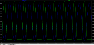
Nice scope dadod!This is my 100W CFA OITPC (OPS serial combination of ClassA and ClassB) clipping, simulated and real amp clipping.
Damir
Just one channel's working, can't find time to repair.Nice scope dadod!
Last edited:
I am looking to the currently URL of this thread (post #1277243) :
http://www.diyaudio.com/forums/showthread.php?postid=1277243#post1277243pl
Thank you for upload the appropriate URL
http://www.diyaudio.com/forums/showthread.php?postid=1277243#post1277243pl
Thank you for upload the appropriate URL
Watching this thread for long. I see many pros and cons of using Mosfets but if used better doesnt Mosfet perform decently?t if the effect was due to strange behavior of Cgd, then the corner frequency of th
Considering the following image attached. Especially in the amplifier OPS than just testing a mosfet on bench with a power supply attached. If you look when current through mosfet is high then VDS is low which gives much better margin in SOA, if there is no drop in VDS then what one says delivering high current pulse of 10ms for higher voltage for a given current to be a point of concern.
Now lets take one case into the scenario take an amp with OPS of +/-90V and there are about 7 pairs of IRFP240/IRF9240 then if the load is 8 ohm then the output current for each mosfet is about 1.3Amp now the SOA of each device itself can take 1.5Amp DC at 90V so now the wave not DC in any chance so consider some more headroom is left over for either back emf or whatever.
Isn`t this a good calculation. I have built a 300WRMS Mosfet Amplifier with 7 pairs of IRFP240/9240 and used considerably large heatsink like about 450mm x 200mm x 50mm deep fins and even a decently loud level of playback the amp was just getting just warm at room temp of 30 deg C. Running since 2 years to drive a 15 inch based pro speaker in a home theater without any problem.
The best thing what I have observed using mosfet the sound has more definition which seems the OPS is capable of rendering the speed given by the IPS. I agree Input stage plays a big role but what is the use if input stage is fast but OPS is not as fast as inputstage?
With the same inputstage the micro detail what I could get out of mosfet is on another level especially in terms of layering of instruments probably all of these because of speed of the OPS.
Attachments
Last edited:
The output stage can only add distortion of varying amounts. Definition and sonic characteristics come mostly from the voltage amp stage and feedback network. It's a system and you can't point to one part and assume that's all it is.
To make that claim, you would have to use the same input stage to drive various output configurations. With some designs I got much lower distortion than the mosfet outputs used. However I'm not going to say that it was the output devices, it was more how they were used.
To make that claim, you would have to use the same input stage to drive various output configurations. With some designs I got much lower distortion than the mosfet outputs used. However I'm not going to say that it was the output devices, it was more how they were used.
Agreed but here I have tested input stage being the same and tested with two OPS with one Bipolar and One mosfet at same voltages and the overall sound is very defined while using Mosfets.
Again, it depends on the configuration. It is entirely possible the bipolar stage did not have an optimum configuration. What you did prove is you like one specific output stage over another - and that's fine.
Now to actually see, you need to measure it and see the spectrum. As soon as you throw personal preference into the mix, all bets are off. Who really knows what the performance is?
Anyway, you like your amplifier. Cool. Without testing you really can't say more than you like that one, not that it is actually better.
Agreed but here I have tested input stage being the same and tested with two OPS with one Bipolar and One mosfet at same voltages and the overall sound is very defined while using Mosfets.
All depend of the exact design, but one thing is sure is that it is quite easier to have low distorsion with a bipolar
output stage than with fets because of the formers s much higher transconductance (gm).
That being said if you put several Fets in parralel there s no reason that very good numbers cant be achived
because gm will increase proportionately to the number of devices, and open loop distorsion will be reduced accordingly,
FI four IRF540 in parralel have about same transconductance as a single bipolar, with lateral fets that have even lower gm
more NFB will be required.

Previously i made a test with a 2 x 20W/4R amp using average darlingtons driven by a discrete basic FE using a differential
and a single transistor VAS, so with quite low 30-35 dB GNFB at 1KHz, also i used a pair of 4R speakers to magnify
the distorsion when reducing the OS idle current, and crossover distorsion is very clearly audible when the OS bias is 0.
I just remade the test with a low power amp using a NE 5532 driving a pair of high gain and very fast Sanken
darlingtons with the same 4R speakers, and this time with 60 dB loop gain at 1KHz there s no clearly audible
crossover distorsion when setting the bias current at 0 despite listening at barely 0.1W peak power.
Typically a non biased EF2 OS has a dead zone that is +- 2.8V, this amount to the power up to 0.25W/8R and 0.5W/4R,
Hence why crossover THD is very high and audible at low level with badly biased OSs that are driven within a low GNFB loop.
60 dB GNFB at 1KHz amount to compress this zone at this frequency to +-2.8mV, in this case crossover distorsion
is at 51 dB lower amplitude than a 1V pk signal and the amplitude of each odd residual is about 2.8mV pk with the total
amplitude being less than 10mV pk.
Now with a single mA OS biasing, wich amount to 0.038S gm, the amplitude of the harmonics will be reduced
by a further 20 dB at 0.28 mV pk for each harmonic, and since there s only odd ones the THD amplitude will be less
than 1mV within a 20kHz bandwith.
So the conclusion is that the conjunction of high enough GNFB and very fast high gain output bipolar devices
render any crossover distorsion anecdotical, not saying that an OS shouldnt be biaised, but all the talks of bipolars
and AB class amp sounding bad, and as a corrolary the claim that class A amps sound better, are just urban legends
that trace their origin in mediocre and incompetently designed amps that have invariably low GNFB ratios, and wich were
linearized as to be somewhat listenable thanks to vast amouts of useless heat.
More to come with a test using Hitachi 2SJ48/2SK133, actually i already checked the thing long ago but it s better
to check again before doing any definitive statement.
As a hint, and despite lower transconductance than bipolars, laterals fets dead zone is much narrower, typicaly +- 0.1V
to +- 0.15V, so in respect of GNFB correction the same will apply.
Last edited:
This is a nice post Wahab and you make valid points. A lot of the anti-class AB is driven by subjectivist hysteria in the same way feedback is. However, people do have preferences for the types of amplifier they like (class A, AB, mosfet, bipolar, tube with/without GNFB etc) and that should not be discounted in the discussion.Previously i made a test with a 2 x 20W/4R amp using average darlingtons driven by a discrete basic FE using a differential
and a single transistor VAS, so with quite low 30-35 dB GNFB at 1KHz, also i used a pair of 4R speakers to magnify
the distorsion when reducing the OS idle current, and crossover distorsion is very clearly audible when the OS bias is 0.
I just remade the test with a low power amp using a NE 5532 driving a pair of high gain and very fast Sanken
darlingtons with the same 4R speakers, and this time with 60 dB loop gain at 1KHz there s no clearly audible
crossover distorsion when setting the bias current at 0 despite listening at barely 0.1W peak power.
Typically a non biased EF2 OS has a dead zone that is +- 2.8V, this amount to the power up to 0.25W/8R and 0.5W/4R,
Hence why crossover THD is very high and audible at low level with badly biased OSs that are driven within a low GNFB loop.
60 dB GNFB at 1KHz amount to compress this zone at this frequency to +-2.8mV, in this case crossover distorsion
is at 51 dB lower amplitude than a 1V pk signal and the amplitude of each odd residual is about 2.8mV pk with the total
amplitude being less than 10mV pk.
Now with a single mA OS biasing, wich amount to 0.038S gm, the amplitude of the harmonics will be reduced
by a further 20 dB at 0.28 mV pk for each harmonic, and since there s only odd ones the THD amplitude will be less
than 1mV within a 20kHz bandwith.
So the conclusion is that the conjunction of high enough GNFB and very fast high gain output bipolar devices
render any crossover distorsion anecdotical, not saying that an OS shouldnt be biaised, but all the talks of bipolars
and AB class amp sounding bad, and as a corrolary the claim that class A amps sound better, are just urban legends
that trace their origin in mediocre and incompetently designed amps that have invariably low GNFB ratios, and wich were
linearized as to be somewhat listenable thanks to vast amouts of useless heat.
More to come with a test using Hitachi 2SJ48/2SK133, actually i already checked the thing long ago but it s better
to check again before doing any definitive statement.
As a hint, and despite lower transconductance than bipolars, laterals fets dead zone is much narrower, typicaly +- 0.1V
to +- 0.15V, so in respect of GNFB correction the same will apply.
@Bonsai, class A amps may sound better in winter if you understand what i m talking about, actually
it s not the amp that sound better as such but the fact that it increase a room temperature and this change
the perception because eardrums are heated and their frequency response is changed by the temperature,
so a sound may then appear as more mellow and/or better defined, so the colder the climate the better class A will sound.
We can also add that a pleasing ambiant temp get one in a better mood and that will also have an influence
in his perception, so the debate is something else than amps characteristics, that s more akin to psycho-acoustics,
and that s before even talking of the room temp influence on the speakers and sound itself.
Indeed it would be curious if one make a test with an AB amp along with powering on some heater that dissipate
say 200W without telling it to the audience, or simply add dummy transistors that just dissipate some heat on the amps
heatsinks to simulate a class A amp, and then tell them that the amp is a A class one, we may have quite some surprises.
Last edited:
A class A amp usually sound pleasing because of monotonic harmonic profile. But not all class A amp can reproduce good stereo imaging or sound stage. It also not all class A amp can sound good at high frequency, airy sound is hard to reproduce. THD and the harmonic profile of the distortion is not the only thing that affect the sound.
So a monotonic harmonic profile with H2 at -80dB is supposed to sound better than a non decreasing harmonic
profile that has all harmonics being at -100 dB if not at -110dB.?
All while listening to this on speakers having distorsion, both THD and IMD, at something like -46 dB at best..?.
And of course with a musical signal knowing that all instruments produce huge amounts of both even and odd
harmonics that are present with their fundamentals notes and wich are the cause of their specific sonic signatures.
There s something in this "logic" that doesnt sound right at all, actually all people doing such claims have not
the slightest idea of what is the spectrum of a musical instrument, they would know that harmonics have
an amplitude that is so high that it s impossible that say 0.1% THD could change the sound even infinitesimaly,
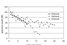
because harmonics can have an amplitude that is comparable to the fundamental.
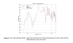
FI here the harmonic spectrum of a piano in function of the hardness of the finger touch and the one of a violin
wich produce much higher levels of harmonics than a piano.
profile that has all harmonics being at -100 dB if not at -110dB.?
All while listening to this on speakers having distorsion, both THD and IMD, at something like -46 dB at best..?.
And of course with a musical signal knowing that all instruments produce huge amounts of both even and odd
harmonics that are present with their fundamentals notes and wich are the cause of their specific sonic signatures.
There s something in this "logic" that doesnt sound right at all, actually all people doing such claims have not
the slightest idea of what is the spectrum of a musical instrument, they would know that harmonics have
an amplitude that is so high that it s impossible that say 0.1% THD could change the sound even infinitesimaly,
because harmonics can have an amplitude that is comparable to the fundamental.
FI here the harmonic spectrum of a piano in function of the hardness of the finger touch and the one of a violin
wich produce much higher levels of harmonics than a piano.
Attachments
Last edited:
Subjective reality meets Objectivist fantasy.
So many amplifiers, so little time.
So many amplifiers, so little time.
👍I found lateral mosfet easier to get good sound (not necessarily low distortion) with simple schematic.
It sound pleasing, not better.So a monotonic harmonic profile with H2 at -80dB is supposed to sound better than a non decreasing harmonic
profile that has all harmonics being at -100 dB if not at -110dB.?
You mix subjectivity with objectivity.
We know how acoustic instruments sound unplugged. So we compare the recording and playback with our memory.
We have taste and preferences also, so sometimes we choose the more pleasing sound than the more accurate sound.
Speakers distorsion being at least 0.5% you are telling me that you can make the dfference between 0.51% THD
since this number is with a -80 dB THD amp, and with 0.501% since that amount to -100dB THD for the amp,
that is that the harmonic profile of those 0.01% and 0.001% added to 0.5% can be detected by our ears.
Actually the only thing that one can find pleasing or unpleasing in such comparisons are the speakers,
rest is pure psychological perception and auto suggestion.
Thing is that two amps with those characteristics can be discriminated the one from the other only when clipping,
the most powerfull one will sound better assuming that both use comparable power supplies that allow decent
power delivery up to their max power.
THD threshold is below 0.5%. There was files that have THD below 0.5% here and several members can detect the different using ABX test.
Why low distortion amplifiers can be detected using high distortion speaker is beyond of my knowledge.
If you can not detect THD threshold (average population), it is your problem.
If you cannot accept ABX test that used some members here, what your test methodology?
Why low distortion amplifiers can be detected using high distortion speaker is beyond of my knowledge.
If you can not detect THD threshold (average population), it is your problem.
If you cannot accept ABX test that used some members here, what your test methodology?
- Home
- Amplifiers
- Solid State
- Bob Cordell Interview: BJT vs. MOSFET