Hi, Mr. Hansen,
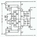
This arrangement is used by Mr. Cordell. Imagine the output transistors are Bipolars, not mosfets. R50-R51 are base stoppers (47ohm). Then after these 47ohms, there are C8+R52 and C9+R53 to ground.
Incase of not using output inductor and not using too big base stoppers, is this R+C to ground after 47ohm helps to overcome negative impedance (when bipolar output stage is headed with capacitive load)?
Attachments
I google, and found these by Dennis Feucht :
http://www.analogzone.com/col_1017.pdf
http://www.analogzone.com/col_1121.pdf
http://www.analogzone.com/col_1017.pdf
http://www.analogzone.com/col_1121.pdf
john curl said:What value would you suggest, Bob?
I really don't know. I just thought I had seen amplifiers with power transistor base stopper resistors on the order of 4.7 or 2.2 ohms. I was just wondering how you arrived at the 10 ohm value, as I'm guessing that the uncertainty of the dc drop though it is causing some of the concern. For example, might it be that fast RET BJTs need a higher value of base stopper resistance for local stability?
Cheers,
Bob
Bob Cordell said:
Yes, I believe that is pretty much correct. There are probably some other time constants involved, but they are likely much less significant. I'm not much good at estimating heat capacities to arrive at the corresponding thermal time constants, however. But they can be measured. I would also tend to guess very roughly that the thermal "mass" of an element is somewhat proportional to its physical mass.
If you look at the SOA vs pulse time for a MOSFET, for example, you can see that it implies that the fastest time constants are measured in milliseconds.
By the same token, its pretty obvious that the time constant of any decent amplifier heat sink is in the minutes.
Cheers,
Bob
For years I've been wondering if sensing temperature on the heat sink was just a bad idea to start with. We have the emitter resistor which provides a measure of the current, and the real goal is constant idle current. We should probably step back and consider throwing out the heat sink sensor, and just derive the bias voltage from the emitter resistor voltage.
Obviously, as I think has been stated before a PIC processor could be used in this application.
Pete B.
It has been tried by LT, but the chip failed to make low high frequency distortion at 20KHz, so necessary for THX. I wasted months of time.
john curl said:It has been tried by LT, but the chip failed to make low high frequency distortion at 20KHz, so necessary for THX. I wasted months of time.
Hi John,
Are you referring to the LT1166?
If yes, a nice idea, but it seems not to have been successful. It seemed like an elegant way of sensing the voltage across RE in the obvious presence of signal. It also, at the same time, in principle eliminated total turn-off of either device in Class-AB.
If it was the LT1166 you were referring to, were you trying it with BJTs or MOSFETs?
BTW, are you at liberty to tell me what the high-frequency THD requirement is for THX is?
Cheers,
Bob
john curl said:It has been tried by LT, but the chip failed to make low high frequency distortion at 20KHz, so necessary for THX. I wasted months of time.
I take it you're suggesting that the bias feedback was modulated by the signal.
Seems to me that with integral control, and a time constant as long as the heat sink thermal system this system should have at least as good distortion performance as the thermal system, and obviously as poor thermal performance. I'd expect that one could use a time constant 10 to 100 times faster than the thermal system and still not disturb the HF distortion performance.
If I were doing this with a processor, I'd look at all the thermal trak diodes to get an estimate of the die temperature, mainly to detect fault conditions, but perhaps also to use adaptive control.
There are many smart control decisions that could be made with a processor.
Pete B.
Bob Cordell said:
If it was the LT1166 you were referring to, were you trying it with BJTs or MOSFETs?
I've tried the LT1166 with both BJT and MOSFET (lateral and vertical). While I never had problems with the THD20 (meaning it was meeting my expectations of around 0.01% - don't know what the THX standard requires) the big problem I've encountered was always clipping. Never had the time to do a throughout analysis, but it appears that the LT1166 was somehow fighting the (standard) I/V circuit, the result being an ugly clipping waveform, sometimes degenerating in an oscillation that was fatal for the power devices.
I was able to consistently stabilize the thing, but the clipping behaviour remained always poor.
Charles, when I made my first RET amplifier back in 1980 or so, I first left out the 10 ohm resistors. Then, John Iverson gave me the suggestion to use them, because I was getting random problems. It worked and I was able to get over 500V/us per side, so I never thought much of the value as being too much and it DOES add a positive R which cancels the negative R is being generated by the cap load and the transistor. However, in analysis of beta balance, I found that 10 ohms to be problematic. I would be happy with 4-5 ohms. That would help me, and probably still keep me safe. After all, like you, I don't use an output coil, but I do use a significant amount of negative feedback, so I have to be more careful.
This will also allow to use cuircit breaker as a protection circuit, sorry John
Re: Re: Re: Re: Re: A question on Lateral's mosfets
A nonlinear curve is still nonlinear even if you add a constant to it.
Charles Hansen said:
Kevin, if you're still reading this thread I wanted to amplify my previous comments.
Yes, you are right that the interelectrode capacitances of semiconductors make pretty ****-poor capacitors. So on paper, one would think that a nice polypropylene capacitor would be much better than that.
But I actually tried that idea many years ago. The non-linear input capacitance of a vertical MOSFET can lead to very high distortion at high power levels and high frequencies. So I thought to myself, "Why not swamp the non-linear capacitance with a nice, linear external capacitor.?"
So I stuck a Wima polypropylene on the gates of the output devices, I think it was 1000 pF or so, and I made a corresponding reduction in the driving impedance of the gain stage to keep the bandwidth constant. It was enough to reduce the non-linearity by a factor of 10 or more. And the amp measured better. But guess what? It didn't sound better, it sounded worse. Not a lot worse, but noticeably worse. Basically, it still had the coloration from the non-linear capacitance of the MOSFET, but now it also had the coloration of the Wima polypropylene cap on top of that.
Another example of a clever idea that is too clever for its own good.
As far as ferrite beads go, I learned the hard way. We used them in our products for a couple of years before I realized that they have inherent problems that make for bad sound. I simply don't recommend their use for audio. I won't even use them for digital audio. Again, use the search function to look for posts under my name with the word "ferrite" and you will see my experiences.
A nonlinear curve is still nonlinear even if you add a constant to it.
RE Sensing Circuit For Output Device Bias
How about this approach? Note-has been only built in my mind.
http://headwize.com/ubb/showpage.php?fnum=3&tid=6770
How about this approach? Note-has been only built in my mind.
http://headwize.com/ubb/showpage.php?fnum=3&tid=6770
Bob Cordell said:BTW, are you at liberty to tell me what the high-frequency THD requirement is for THX is?
The onerous non-disclosure agreement precludes this. The
true requirements for high fidelity in home theater must be kept
a deep dark secret.
😎
Hint: Luke, I am your father...
john curl said:That's just like Holman. I was just being stubborn!😀
You don't like Tom Holman?
I guess I'm in good company 🙂.
He is a brilliant person in the audio business, and a pleasant gentleman at that.
Bob
hitsware said:>http://www.diyaudio.com/forums/attachment.php?s=&postid=484803&stamp=1096758143
That's because it's a 'common emitter' output stage.
Thermal stuff is amplified to the extent of the voltage gain of the stage.
The question under consideration was runaway, before the "thermal stuff" has a chance to respond. A quick look at that amp suggests to me that it is flawed from a thermal stability standpoint, but I've not dug into the details.
Pete B.
PB2 said:
The question under consideration was runaway, before the "thermal stuff" has a chance to respond. A quick look at that amp suggests to me that it is flawed from a thermal stability standpoint, but I've not dug into the details.
Pete B.
Hi Pete,
I haven't looked at it real hard, but I'll take a chance here and speculate that, with the right interpretation, it may also be governed by my equation, as long as the right numbers are plugged in.
It looks like the net transconductance of the each output transistor, with respect to changes in bias spread, is, in this case, about equal to the transconductance of the power transistor in combination with its associated RE, just like in the emitter follower cases. I say this because the "gain" in this mode provided by the driver transistor (and ignoring its gm in comparison to 100 ohms), is about unity, since we have 100 ohms in the emitter to ground and 100 ohms in the collector load. This also ignores the input impedance of the output transistor (Beta is assumed to be high).
Cheers,
Bob
Originally posted by john curl It has been tried by LT, but the chip failed to make low high frequency distortion at 20KHz, so necessary for THX. I wasted months of time.
Hi John,
If you had used a simulator (as I did), you had only wasted one hour.
Cheers, Edmond.
OT Paper
Anyone have this paper scanned? I have it and will scan it if not, if anyone has is scanned already I'd appreciate an email of it.
"Distortion in low-noise amplifiers" by Eric F. Taylor, Wireless World August, 1977
and also the September part 2 issue?
Pete B.
Anyone have this paper scanned? I have it and will scan it if not, if anyone has is scanned already I'd appreciate an email of it.
"Distortion in low-noise amplifiers" by Eric F. Taylor, Wireless World August, 1977
and also the September part 2 issue?
Pete B.
- Home
- Amplifiers
- Solid State
- Bob Cordell Interview: BJT vs. MOSFET