I have two PCBs that I will use together. The boards have a number of jumper locations on them. These jumper locations are actually just through-holes with standard spacing, so you can solder directly to them or use pin headers or terminal blocks, etc. Only some pins need to connect from one board to the next.
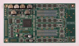
Specifically, this is the Soekris dam1021 DAC board. Manufacturer link. Big diyAudio thread. I attached the manufacturer's pic below. It's that far-left header that some holes need to connect to the partner board. I intend to stack the partner boards on top of each other.
What is the "best" way to accomplish this selective pin mating? These are I2S wires, which should be kept as short as possible. The "easy" way would be to fabricate some "Y" jumper wires. But what I have in mind is something like one of the following:
Problem with the first option is, I can't seem to find any of these "T" jumper wires (not even sure if such a thing exists).
Problem with the second option is, I don't know if a "jumper pole" exists, and also, I'm not sure where to find the header pins that are long enough to be usable on both sides of the PCB.
Specifically, this is the Soekris dam1021 DAC board. Manufacturer link. Big diyAudio thread. I attached the manufacturer's pic below. It's that far-left header that some holes need to connect to the partner board. I intend to stack the partner boards on top of each other.
What is the "best" way to accomplish this selective pin mating? These are I2S wires, which should be kept as short as possible. The "easy" way would be to fabricate some "Y" jumper wires. But what I have in mind is something like one of the following:
- Top board has pin headers pointing down. Bottom board has pin headers pointing up. I use a "T" jumper wire, where one end of the wire has opposing female connectors, so I could simultaneously connect the top and bottom boards with one jumper wire.
- One board has headers on both the top and bottom. Then I run a regular jumper to the top headers. Then I get a female-to-female "jumper post" to connect the header pins on the bottom of the top board to the pins on the top of the bottom board.
Problem with the first option is, I can't seem to find any of these "T" jumper wires (not even sure if such a thing exists).
Problem with the second option is, I don't know if a "jumper pole" exists, and also, I'm not sure where to find the header pins that are long enough to be usable on both sides of the PCB.
Attachments
I'm not sure I understand completely, so... some of the pins on J3 need to be connected to 2 different boards, yes? Do the other 'partner' boards have headers with the same number of pins, and are the pins that need to be connected in the same locations they are on J3?
If this is correct, how about using right-angle headers with ribbon cable daisy-chained between the boards. The pins you don't need can be cut at the header, and you can make the cable very short. I've done something very similar to create a data bus and the boards were about 1/2" apart. Of course making a ribbon cable that short is a bit of a challenge.
If this is correct, how about using right-angle headers with ribbon cable daisy-chained between the boards. The pins you don't need can be cut at the header, and you can make the cable very short. I've done something very similar to create a data bus and the boards were about 1/2" apart. Of course making a ribbon cable that short is a bit of a challenge.
I'm not sure I understand completely, so... some of the pins on J3 need to be connected to 2 different boards, yes? Do the other 'partner' boards have headers with the same number of pins, and are the pins that need to be connected in the same locations they are on J3?
A picture says 1000 words, so take a look at diyAudio member Spikestabber's balanced dual mono dam1021 build. It's hard to see exactly how he paralleled J3 in those pics, but at least you get some of the idea.
I'm going for virtually the same thing he did, which is using exactly two boards in parallel. In theory, there could be more than two boards in parallel, but that's beyond the scope of my question. 🙂
So when two boards are paralleled, some pins are from one board are tied to the other, and some are not. But when two pins are tied together, they are the exact same pin on each board. (For example, board_1 J3 pin5 will tie to board_2 J3 pin5.)
If this is correct, how about using right-angle headers with ribbon cable daisy-chained between the boards. The pins you don't need can be cut at the header, and you can make the cable very short. I've done something very similar to create a data bus and the boards were about 1/2" apart. Of course making a ribbon cable that short is a bit of a challenge.
Did you ever work with older computer hard drives by chance? Before SATA, we had PATA (parallel ATA, as opposed to the newer serial ATA). PATA was also called IDE. But those were big fat ribbon cables that did exactly what you describe. They were 80-pin (2x40) so could probably be cut to size for this exact application. Although they were usually well over 10cm in length, which is the max recommended length for I2S.
Still, a good idea IMO!
However, I think I found a solution, which is to simply use really long pin headers. In particular, on the "bottom" board I'll use normal male pin headers. On the "top" board, I'll get a female pin header block with really long leads. The female part will be mounted facing down, so it can directly mate to the male pins of the bottom board. The extra long pins will stick out the top and I can connect leads from my I2S/SPDIF devices.
I found these header pins on AliExpress by searching for stacking or stackable header 2x13. Here is a link to a representative example. Most of the matching products also had Raspberry Pi in the description, so I assume this kind of board stacking is common in the RPi world.
I thought about the stacking idea, but I did a quick search on the Samtec website (what a mess!) and the ribbon cable thing was the easiest alternative I could think of.
All in all though, since you've found the right parts, using stacking headers is the way to go.
Bill
All in all though, since you've found the right parts, using stacking headers is the way to go.
Bill
- Status
- Not open for further replies.