I have not decided whether I can risk doing the full -80dB in one stage and just accept the errors due to capacitance, or go for a two stage attenuator.
With a one stage arrangement all inside a BNC connector I only need 2 resistors and that easily fits.
That's a 10k series resistor into a 1r0 shunting resistor to feed into the 100ohms input impedance of the inverting first stage of the LNA. Basically copying the jury rigged RCA I have tried.
or
a two stage needing 4 or 5 resistors which might not fit inside unless I use some smd for the later stages keeping the first as a 600mW leaded metal film.
This becomes a series 1k0 10r2 for shunt first stage, then series 100r to 1r0 shunt feeding into the 100r inverting.
The 10r2 can be replaced with a parallel pair of 15r||47r and give reasonable accuracy.
I have all of 1r, 15r, 47r, 100r and 1k in 805 smd and in 600mW leaded metal film.
two questions from which I should be able to decide.
Q1.
should I build two stage rather than one stage?
Q2,
should I split the two stages into two separate BNC adaptors or try to fit both inside a single BNC adaptor using mostly 805 smd metal oxide?
Hello Andrew,
Maybe, the most multi-purpose solution is a stepped attenuator as Elevee show.
I've made a DIY one, for nearly nothing. The full enclosure is made with some
epoxy copper clad soldered together.
I use it very often with my instruments.
It looks like this :
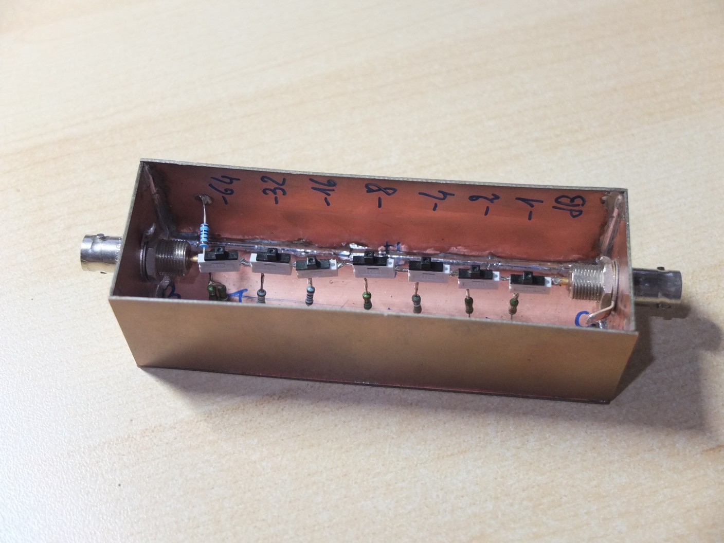
The range is 0 to -120 dB in 1dB step with 7 switches.
I used only standard MRS25 resistors, so the HF response is not so good than real RF attenuator.
Anyway, even with 120db attenuation, the error at 100kHz is very low. Sufficient for my use.
(I would love to build a better one, many idea about that, but already too busy by others projects!).
The Zin is 1k constant and Zo is between 0 to 470 Ohms.
You can compute all value and choose Zin or Zout constant using this
very good on-line calculator HERE.
Hope that will help you 🙂
Frex
Maybe, the most multi-purpose solution is a stepped attenuator as Elevee show.
I've made a DIY one, for nearly nothing. The full enclosure is made with some
epoxy copper clad soldered together.
I use it very often with my instruments.
It looks like this :
The range is 0 to -120 dB in 1dB step with 7 switches.
I used only standard MRS25 resistors, so the HF response is not so good than real RF attenuator.
Anyway, even with 120db attenuation, the error at 100kHz is very low. Sufficient for my use.
(I would love to build a better one, many idea about that, but already too busy by others projects!).
The Zin is 1k constant and Zo is between 0 to 470 Ohms.
You can compute all value and choose Zin or Zout constant using this
very good on-line calculator HERE.
Hope that will help you 🙂
Frex
Hi Andrew,
There is a good reason why attenuators are only made to a certain level. The largest BNC or N connector I have is 30 dB. Also, don't ignore the capacitive component. You could use a trimmer (surface mount) and correct the pad using a square wave. Same as for a 'scope probe. That is in effect what you are making.
At least try your chosen attenuator out with compensation to get a handle on what your error is likely going to be.
There is an advantage using a low impedance standard. With sources at 50R, noise pickup is not as much of a problem compared to high impedance audio types that might sit at 10K. If you prototype the thing, you can make an intelligent decision for compensation.
-Chris
It is workable: the capacitance of the 10K should let you reach >10MHz, if you are careful not to add anything on top of that with a poor construction, and the accuracy won't be great, because with one ohm foot resistor, some milliohms here and there will make some damage without you even realizing, but it can work.That's a 10k series resistor into a 1r0 shunting resistor to feed into the 100ohms input impedance of the inverting first stage of the LNA.
Note that with such extreme values, the series inductance of the 1 ohm will be as damaging, if not more than the capacitance, and will work in the same direction.
That said, for 100kHz, it should remain acceptable
One will work, but with some limitations as I said aboveQ1.
should I build two stage rather than one stage?
Having two distinct attenuators will probably prove useful at some time: you may need both at the same time at different locations, and you have the option of using only 40dB for example when you need no more. More flexibility is always valuableQ2,
should I split the two stages into two separate BNC adaptors or try to fit both inside a single BNC adaptor using mostly 805 smd metal oxide?
- Status
- Not open for further replies.