Hi.
I have a Blue Robbie that does not work.
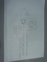
I have a schematic that I found online, unfortunately it is missing the PSU and not very accurate...
Apparently the problem is in the heater supply voltages: one rail has -48V and the other one -54V (6V difference). That is measured without a tube. As soon as I put a tube in the socket, the -54V rail collapses to -48V (-48V on both rails = no heater voltage).
The tube is a Russian made 6N23P. Its basically the same as the ECC88 (European) or 6DJ8 (American). These tubes only run on 6.3V heater supply.
The 6N23P had the contact pins corroded (discovered this while checking the tube on my tube tester), so I scrapped them clean.
I also checked with another working ECC88 NOS Siemens.
There is the main PCB and the tube-socket PCB, held together with an edge connector. I cleaned this one and bent the contacts back into place.
Still doesn't work...
Here is what I did on the main PCB:
- visually inspected all electrolytic caps for leakage, swollen, etc. Since the Robbie worked while it was new, I guess that the polarities of these caps are correct...
- took out all (ALL) electrolytic caps and checked them for short or open with a digital volt meter (DVM) set on resistance. If R rises or falls then the caps usually are working.
- took out and checked all (again, ALL) transistors from the circuit. Same DVM, this time set on diode test.
- did the same with all diodes...
The circuit board of this Robbie is not in the nicest shape, so sending the Robbie back to the factory is not an option.
Any suggestions what else I could check?
I have a Blue Robbie that does not work.
I have a schematic that I found online, unfortunately it is missing the PSU and not very accurate...
Apparently the problem is in the heater supply voltages: one rail has -48V and the other one -54V (6V difference). That is measured without a tube. As soon as I put a tube in the socket, the -54V rail collapses to -48V (-48V on both rails = no heater voltage).
The tube is a Russian made 6N23P. Its basically the same as the ECC88 (European) or 6DJ8 (American). These tubes only run on 6.3V heater supply.
The 6N23P had the contact pins corroded (discovered this while checking the tube on my tube tester), so I scrapped them clean.
I also checked with another working ECC88 NOS Siemens.
There is the main PCB and the tube-socket PCB, held together with an edge connector. I cleaned this one and bent the contacts back into place.
Still doesn't work...
Here is what I did on the main PCB:
- visually inspected all electrolytic caps for leakage, swollen, etc. Since the Robbie worked while it was new, I guess that the polarities of these caps are correct...
- took out all (ALL) electrolytic caps and checked them for short or open with a digital volt meter (DVM) set on resistance. If R rises or falls then the caps usually are working.
- took out and checked all (again, ALL) transistors from the circuit. Same DVM, this time set on diode test.
- did the same with all diodes...
The circuit board of this Robbie is not in the nicest shape, so sending the Robbie back to the factory is not an option.
Any suggestions what else I could check?
Either the heater in the valve has become shorted or a bad connection or the transformer is kaput.
Heater in the valve does work when I check it in my valve tester. And when I put another valve into the Robbie it doesn't glow, either. I use an ECC88 Siemens NOS that I have on hand (substitute for the 6N23P) This one does work in some condenser mics, for example.
The transformer (when connected and the Robbie switched on) works, I get +48V and -48V, and also -54V, only with no tube is inserted into the socket. So, the transformer is not kaputt.
That leaves a bad connection (or any issue, unknown to mankind).
I tested for continuity between each female pin on the tube socket and then between the socket and the terminals on both sides of the edge connector, and everything checks out ok, even those lines that have resistors or caps in its path.
The strange thing is that as soon as I put the valve into the Robbie, the -54V becomes -48V. After turning off the preamp and taking out the tube and turning it on again, it resets itself to -54V.
At one time, after replacing a 78M06 regulator (rated at 700mA peak current) with a LM7806 (rated at 1A) on the main PCB, I managed to see the tube starting to glow for a really short time, but when I connected it to my console it had shut down already.
I thought it was the new regulator but when I took out the tube (Robbie off - tube out - Robbie on) and measured the rails there were -48V and -54V.
I destroyed the 78M06 trying to take it out of the circuit for testing. It doesn't show up on the schematic but it is there, on the underside of the board.
Fold-back current limiting on a cold heater? The fact that a 7806 did slightly better than 78M06 supports this hypothesis. This is a common problem with naive DC regulated valve heaters.
Or it could be thermal shutdown of the regulator if the heatsinking is inadequate.
Or it could be thermal shutdown of the regulator if the heatsinking is inadequate.
Interesting point. Unfortunately I do not understand that concept well enough.
How would you solve this problem?
The 7806 is a TO220 type. The heatsink is fixed with thermal paste and then with a screw in order to hold it in place. I could also try to solder the heatsink to the place on the PCB where the original 78M06 was located. Since pin 2 is ground on either IC (78M06 and 7806), so I soldered it to ground. On the original 78M06 it was cut off.
Try to draw too much current and the regulator will reduce output voltage so you actually end up with less current. Put too little current through the valve heater and it will never heat up enough to draw the correct current. As I said, this is a common problem with heater regulators. Three solutions:PhantomBox said:Unfortunately I do not understand that concept well enough.
1. regulate current instead
2. don't regulate at all
3. regulate to a higher voltage and add a series resistor
The 6N23P filaments have a current draw of approx. 285 to 350mA.
That's well in the ballpark for either the 78M06 or LM7806.
Since no schemo of the PSU available, I'll try to explain it the best I can:
From the "+" terminal of the only rectifier on the PCB, +12V goes to input (pin1) of the 7806, passing on the positive side of a 2200uF/16V electrolytic cap. The negative side of the cap is connected to 7806 GND (pin2) which then is connected to a separate path carrying -54V to the heater rail pin4 on the valve socket. 7806 output (pin3) is connected to virtual GND (w/o regulator) on the +/-48V rails.
Answer to solution 1:
For 78XX (= positive fixed regulator) used as current regulators, output voltage V / R = output current A. In this case: 6V / 18ohm = 0.33A
Would that still apply if I add an 18ohm resistor to pin3 but take my output from pin2?
Answer to solution 2:
If I don't regulate at all, what would you suggest I change / add / remove on the circuit?
Answer to solution 3:
I guess there are lots of formulas to calculate the voltage drop from "X"V to 6VDC... 😉
This seems like another interesting option.
When hot. When cold, expect something in the region of 1-1.5A for a few seconds. If the regulator is fed from a 12V supply then I would expect the 7806 to get too hot if the heatsink only allows for 0.3A current draw, so it would do a thermal shutdown. The 78M06 will, as already said, do an overcurrent shutdown.PhantomBox said:The 6N23P filaments have a current draw of approx. 285 to 350mA.
That's well in the ballpark for either the 78M06 or LM7806.
No, just one formula: have you heard of Ohm's Law?I guess there are lots of formulas to calculate the voltage drop from "X"V to 6VDC...
I think that the 2.2 ohm 1W 5% resistor that is before the rectifier has risen to 2.9 ohm, but I don't know if this has anything to do with the 6N23P filaments not heating up...
(2.2 ohm +/- 5% = max. 2.31 ohm / min. 2.09 ohm)
(2.2 ohm +/- 5% = max. 2.31 ohm / min. 2.09 ohm)
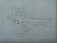
I added a schematic (no criticism allowed!) of the actual heater power supply on the Robbie main PCB. I also added a possible current limiting resister to that schematic.
Feel free to comment / suggest / improve.
Again, don't criticize my schematic!
Feel free to comment / suggest / improve.
Again, don't criticize my schematic!
That could be because it is overheating every time you switch on. It can handle the normal running current but not the starting current.PhantomBox said:I think that the 2.2 ohm 1W 5% resistor that is before the rectifier has risen to 2.9 ohm
18 ohms is far too big.I also added a possible current limiting resister to that schematic.
I would remove the 2.2 ohms resistor before the rectifier. Use a 9V regulator. Add a 10 ohm resistor in series with the DC output.
Didn't work. Now I don't even get the 6V difference (-48V to -54V) for the heater filaments on just the main PCB, without attaching the tube socket PCB.
Something must have gone terribly wrong, or I missed to connect something.
I'll have to check the whole circuit again...
Something must have gone terribly wrong, or I missed to connect something.
I'll have to check the whole circuit again...
- Status
- Not open for further replies.
- Home
- Live Sound
- Instruments and Amps
- Blue Robbie heater problems