Yes, heatsinks are undersized due to chassis dimension (I recycled it from another project, as you can see from tha various holes and patches), but do their job for normal room listening. Unfortunately my power supply is +/-40 volts. With +/-30 V supply these heatsinks should support full power dissipation. Owever, after a few hours playing at medium volume, the chips are hot, but still you can touch them.Nice micro-controlled amp. You really need cabinet ventilation! Why the very thick isolator pads on the ICs?
I bought the isolators online, and I did read 0.3 mm... they're actually 3 mm. They sure do they're isolating function😀
Vent the cab and the things will be cooler.
What is the thermal resistance of the pads under the area of the IC? 3mm is quite thick and I'd be concerned with short term dissipation.
What is the thermal resistance of the pads under the area of the IC? 3mm is quite thick and I'd be concerned with short term dissipation.
It needs big vents through the cabinet, directly underneath the heatsinks and also feet on the bottom of the enclosure, plus output vents at/near the top of the enclosure.
Also, change the big power caps that are located near the chip to 220uF.
Also, change the big power caps that are located near the chip to 220uF.
Sure, I've already considered to make venting holes.Vent the cab and the things will be cooler.
What is the thermal resistance of the pads under the area of the IC? 3mm is quite thick and I'd be concerned with short term dissipation.
Rth of the pad should be 0.6 C/W, the Rth-jc of TDA7294 is 1.5 C/W and Rth of heatsink is 1.4 C/W. Adding .5 C/W for the case-pad-sink coupling the total Rth is 4 C/W.
With +/-30 V supply the maximum power dissipation is 25W, so the internal cabinet temp can reach 45 degrees C before activation of TDA7294 thermal protection.
For +/-40 V supply, I absolutely need larger heatsinks.
Are my calculations right?
Can you explain me why?Also, change the big power caps that are located near the chip to 220uF.
One is the feedback cap (and is already 220u), the other is the bootstrap and is 47u (the application note suggest 22u).
Those values are probably close to perfect.Can you explain me why?
One is the feedback cap (and is already 220u), the other is the bootstrap and is 47u (the application note suggest 22u).
Sorry, I thought they were power decoupling caps.
I think that you need to add good power decoupling to cool it off some.
So, in this case, Add some 220u power decoupling caps extreeeeeeeeeeeeeeeemly close to each chip. 😀
Edit: In addition to the 220u power decoupling cap for pin 7 And the 220u power decoupling cap for pin 8, you can add one (1) 2uF polyester cap between pin 13 and pin 15.
Edit2: Without proper decoupling, or if it is too small, or if it is too large, or if it is too far away, the chip explodes.
Last edited:
No, because the TDA7294 is not durable at that voltage. The derating is insufficient.For +/-40 V supply, I absolutely need larger heatsinks. Are my calculations right?
For +/- 40vdc rails, you need TDA7293 chips.
When using TDA7293, the board should be slightly different per the bootstrap hookup, but it is a little bit better performer too (if when using TDA7293 specific boostrap hookup).
Thank you Daniel.
Actually I have 2200uF decoupling caps as close as possible to each chip plus 100nF smd near the supply pins. I'll try to find place for the 2uF rail-to-rail decoupler.
Probably you're right, I'm stressing the chips too much with 40 volts. I'll consider trying the 7293.
Thanks again.
Actually I have 2200uF decoupling caps as close as possible to each chip plus 100nF smd near the supply pins. I'll try to find place for the 2uF rail-to-rail decoupler.
Probably you're right, I'm stressing the chips too much with 40 volts. I'll consider trying the 7293.
Thanks again.
I think when you disconnect the power cord, PIC micro shut down immediately causing incorrect mute/standby sequence.Hello everybody.
After reading all the threads on this chip, I keep on make them blow.
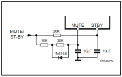
I've built an amplifier based on a TDA7439 (input selector, tone and volume control) and two TDA7294 as power stage. The system is controlled by a PIC micro (with a rotary encoder, two buttons and an LCD display) driving TDA7439 I2C bus and TDA7294 mute and stby pins. Initially, I tested the amplifier for several months with the micro board always powered (connected to a separate 5V power supply), and the results was very good. Clear sound with no pop, hum or other noises. Pressing the standby button put the TDA7294 in standby with the correct sequence, mute first, than standby, and disconnecting the amplifier power cord, the amp shut down quietly. The problems arised when I put all together in the chassis. Now disconnecting the power cord (or turning the mains switch off) cause the two power supplies to switch off at the same time. The result: the TDA7249 blow immediately. I've blown 5 (five) chips one after another only switching the amplifier off. I'm really disappointed, cause I was very satisfied of the audio quality, so,before giving up with ST and migrate toward National chips, I'd like to know if someone could help me to solve this enigma. I attach a schematic (it's not complete, only the relevant part).
Here are some additional information:
- the chips were genuine parts (obtained directly from ST as free samples);
- the mcu detect the power fail condition and immediately put the TDA7249 in mute;
- in one occasion, the chip exploded with the mcu mute and stby pins disconnected (this should be the condition showed in fig. 1 of th datasheet, when mute and stby switches are open, so why explode?).
Many thanks in advance and sorry for the long post.
may be it better using single control circuit connected to micro like this circuit
Attachments
I would expect that the PSU capacitor is large enough to power the PIC long enough to shut down properly. Maybe even several minutes.
Thanks greenocean, but this is not the case.I think when you disconnect the power cord, PIC micro shut down immediately causing incorrect mute/standby sequence.
may be it better using single control circuit connected to micro like this circuit
When power goes down the pic detects it immediately and puts the amp in mute, then in standby.
I think a few hundreds mS are sufficient for the above procedure.I would expect that the PSU capacitor is large enough to power the PIC long enough to shut down properly. Maybe even several minutes
Last edited:
Sure, I've already considered to make venting holes.
Rth of the pad should be 0.6 C/W, the Rth-jc of TDA7294 is 1.5 C/W and Rth of heatsink is 1.4 C/W. Adding .5 C/W for the case-pad-sink coupling the total Rth is 4 C/W.
With +/-30 V supply the maximum power dissipation is 25W, so the internal cabinet temp can reach 45 degrees C before activation of TDA7294 thermal protection.
For +/-40 V supply, I absolutely need larger heatsinks.
Are my calculations right?
Rth of the pad may measured over its entire area. The thermal contact area on the IC is quite a bit smaller. I'd be inclined to attach a thermal probe to the IC and measure the temp while playing sine tones into a noninductive load at max dissipation point.
Sounds like the problem is fixed. The trick is to look at every pin and make sure that as the power supply comes up or shuts down, that no pin can become biased outside the range of the datasheet limits compared to the other pins at that instant. Diode clamp anything where it might be a problem. Sometimes series limiting with a resistor is a good idea. Clamp, limit, snub or regulate to prevent excess PS voltage (spikes or whatever) during power up or down. That can be a bit difficult if you're running close to the limits, especially under high line conditions.
These pad's Rth is 0,3 C/W per square inch, so I roughly calculated the 0.6 C/W value for about half square inch contact area. Is it right?.Rth of the pad may measured over its entire area. The thermal contact area on the IC is quite a bit smaller. I'd be inclined to attach a thermal probe to the IC and measure the temp while playing sine tones into a noninductive load at max dissipation point.
Anyway, I'll go with practical measurments.
Thanks.
Ah, for cooler running, clearer sound and less trouble with TDA7293/4/5/6, try 220uF||220uF (440uF) instead of the 2200uF.Thank you Daniel.
Actually I have 2200uF decoupling caps as close as possible to each chip plus 100nF smd near the supply pins.
Pier,
I don't have that chipamp to hand, but I would expect the area to be less than half a square inch.
I'm thinking around 0.34square inches
This gives Rth c-s ~0.9C/W
Remember to de-rate the sink, if delta T is less than 70 to 80 C degrees.
I don't have that chipamp to hand, but I would expect the area to be less than half a square inch.
I'm thinking around 0.34square inches
This gives Rth c-s ~0.9C/W
Remember to de-rate the sink, if delta T is less than 70 to 80 C degrees.
It could be amp PSU is discharging leaving PIC outputting 5 volts into mute and stdby and latching up the TDA. Simple fix is to have mute and stdby have a diode to amp +ve rail.
I did a similar circuit with a IRS2092 and it kept blowing.
In the end I used opto-couplers to hold irs2092 in reset.
I would use +/-35V rails.
The 7294 is fussy about the feedback resistor. It must be close to pins as possible.
If not the 7294 can oscillate and burn up.
I did a similar circuit with a IRS2092 and it kept blowing.
In the end I used opto-couplers to hold irs2092 in reset.
I would use +/-35V rails.
The 7294 is fussy about the feedback resistor. It must be close to pins as possible.
If not the 7294 can oscillate and burn up.
Last edited:
What happened to you is this. The leg 8 ( I think see pdf) is the - V of the chip and is connected to the back plate of the chip. If you don't isolate the chip from the sink and you install the sink to chassis you get a sort circuit because the chassis is connected to ground. So it's blown
- Home
- Amplifiers
- Chip Amps
- Blown TDA7294