Hello everybody.
After reading all the threads on this chip, I keep on make them blow.
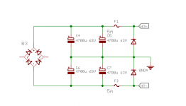
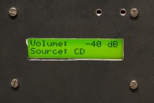
I've built an amplifier based on a TDA7439 (input selector, tone and volume control) and two TDA7294 as power stage. The system is controlled by a PIC micro (with a rotary encoder, two buttons and an LCD display) driving TDA7439 I2C bus and TDA7294 mute and stby pins. Initially, I tested the amplifier for several months with the micro board always powered (connected to a separate 5V power supply), and the results was very good. Clear sound with no pop, hum or other noises. Pressing the standby button put the TDA7294 in standby with the correct sequence, mute first, than standby, and disconnecting the amplifier power cord, the amp shut down quietly. The problems arised when I put all together in the chassis. Now disconnecting the power cord (or turning the mains switch off) cause the two power supplies to switch off at the same time. The result: the TDA7249 blow immediately. I've blown 5 (five) chips one after another only switching the amplifier off. I'm really disappointed, cause I was very satisfied of the audio quality, so,before giving up with ST and migrate toward National chips, I'd like to know if someone could help me to solve this enigma. I attach a schematic (it's not complete, only the relevant part).
Here are some additional information:
- the chips were genuine parts (obtained directly from ST as free samples);
- the mcu detect the power fail condition and immediately put the TDA7249 in mute;
- in one occasion, the chip exploded with the mcu mute and stby pins disconnected (this should be the condition showed in fig. 1 of th datasheet, when mute and stby switches are open, so why explode?).
Many thanks in advance and sorry for the long post.
After reading all the threads on this chip, I keep on make them blow.
I've built an amplifier based on a TDA7439 (input selector, tone and volume control) and two TDA7294 as power stage. The system is controlled by a PIC micro (with a rotary encoder, two buttons and an LCD display) driving TDA7439 I2C bus and TDA7294 mute and stby pins. Initially, I tested the amplifier for several months with the micro board always powered (connected to a separate 5V power supply), and the results was very good. Clear sound with no pop, hum or other noises. Pressing the standby button put the TDA7294 in standby with the correct sequence, mute first, than standby, and disconnecting the amplifier power cord, the amp shut down quietly. The problems arised when I put all together in the chassis. Now disconnecting the power cord (or turning the mains switch off) cause the two power supplies to switch off at the same time. The result: the TDA7249 blow immediately. I've blown 5 (five) chips one after another only switching the amplifier off. I'm really disappointed, cause I was very satisfied of the audio quality, so,before giving up with ST and migrate toward National chips, I'd like to know if someone could help me to solve this enigma. I attach a schematic (it's not complete, only the relevant part).
Here are some additional information:
- the chips were genuine parts (obtained directly from ST as free samples);
- the mcu detect the power fail condition and immediately put the TDA7249 in mute;
- in one occasion, the chip exploded with the mcu mute and stby pins disconnected (this should be the condition showed in fig. 1 of th datasheet, when mute and stby switches are open, so why explode?).
Many thanks in advance and sorry for the long post.
Attachments
Last edited:
I can't see anything wrong with either the PSU, or the amplifier, sch.
I can't check the PIC.
Check that you have the correct voltages feeding the amplifier.
Do both polarities shut down together?
Do either of the fuses blow/survive?
I can't check the PIC.
Check that you have the correct voltages feeding the amplifier.
Do both polarities shut down together?
Do either of the fuses blow/survive?
Thank you Andrew.I can't see anything wrong with either the PSU, or the amplifier, sch.
Check that you have the correct voltages feeding the amplifier.
Do both polarities shut down together?
Do either of the fuses blow/survive?
All voltages are ok, +-40 volts for tha amp and +5 volts for the logic.
In one occasion the positive fuse did blow.
The only problem that I can imagine is that the mcu power collapses to fast.
The pic remain powered for a few hundreds ms; during this time it put the amp in mute (as soon as it detect power down) and stores various parameters in EEPROM.
Owever, even with the pic not powered I can't understand what's wrong.
I/O pins should go in a high impedance state, or at zero potential.
My next attempt will be to put a buffer battery to keep the logic powered, than I will give up trying.
Thanks.
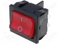
What kind of power switch do you use? Is there possibility of voltage spikes while switching off?
It's a common dpst rocker switch.What kind of power switch do you use? Is there possibility of voltage spikes while switching off?
Attachments
Ah !
catch diodes from spkr output to both power rails, after the fuses.
catch diodes from power ground to both power rails, after the fuses.
catch diodes from spkr output to both power rails, after the fuses.
catch diodes from power ground to both power rails, after the fuses.
Try adding some catch diodes from the output to the supplies
Something like this (see attached images)?Ah !
catch diodes from spkr output to both power rails, after the fuses.
catch diodes from power ground to both power rails, after the fuses.
Could you explain me their function?
Do you think their absence could cause the chip explosion?
Thank you very much.
Attachments

Not sure about this chip, but I've seen odd behavior when the incorrect voltage is put on the mute standby pin (or pins) on some of ST's ICs. I've made the TDA7264 conduct heavy current when the M/STBY pin is connected to 0v. The TDA7294 has a different arrangement so may or may not have this issue.
Throwing parts at it is not how you fix problems. You need to analyze the circuit at power down to see what is going on. Limit current going to the power pins so you don't keep blowing up ICs. Take measurements. An oscilloscope is a handy tool when checking these dynamic situations.
Throwing parts at it is not how you fix problems. You need to analyze the circuit at power down to see what is going on. Limit current going to the power pins so you don't keep blowing up ICs. Take measurements. An oscilloscope is a handy tool when checking these dynamic situations.
Not sure about this chip, but I've seen odd behavior when the incorrect voltage is put on the mute standby pin (or pins) on some of ST's ICs.
Hi,
I've noticed in earlier posts on this forum that the correct state on the muting pin is important with this chip. Also, if pre rails have additional filtering it is very important to make sure how pre and power rails relate to each over.
Member ilimzn has posted lots of valuable info regarding TDA7294. For example here.
Last edited:
Solved (maybe)
In contrast with my suppositions, the real cause seems to be the switch.
I've made a lot of empiric tests roughly disconnecting power cord, and there's no problem at all. The amp shut down quietly like it's supposed to do.
I forgot to say that the switch is the illuminated type (neon bulb); could it be the cause of my troubles?
Now, what do you think should be the solution?
1: Get rid of the switch and smash it with a big hammer;
2: Use a different switch;
3: Put some protection on the switch to avoid it causing problems;
4: Protect the amplifier from troubles caused by the switch (catch diodes as Jaycee and Andrew suggested);
One last question:
given the sensitivity to this sort of problem, should I worry about similar events caused, say, by switch external to the amplifier (mains breaker, multiple-socket switch, etc.).
Thank you very much.
Thanks to everybody for the replies.Ah !
catch diodes from spkr output to both power rails, after the fuses.
catch diodes from power ground to both power rails, after the fuses.
In contrast with my suppositions, the real cause seems to be the switch.
I've made a lot of empiric tests roughly disconnecting power cord, and there's no problem at all. The amp shut down quietly like it's supposed to do.
I forgot to say that the switch is the illuminated type (neon bulb); could it be the cause of my troubles?
Now, what do you think should be the solution?
1: Get rid of the switch and smash it with a big hammer;
2: Use a different switch;
3: Put some protection on the switch to avoid it causing problems;
4: Protect the amplifier from troubles caused by the switch (catch diodes as Jaycee and Andrew suggested);
One last question:
given the sensitivity to this sort of problem, should I worry about similar events caused, say, by switch external to the amplifier (mains breaker, multiple-socket switch, etc.).
Thank you very much.
Add the output catch diodes, and put an X2 rated capacitor across the switch as a "spark killer". If you really want to go the whole hog, fit a MOV across the mains input, after the mains-side fuse.
You're right, that's what I'm trying to do. I'm not looking for a solution, I want to understand what the problem is. Unfortunately I only own an analog oscilloscope, not enough for an accurate analisys.Throwing parts at it is not how you fix problems. You need to analyze the circuit at power down to see what is going on. Limit current going to the power pins so you don't keep blowing up ICs. Take measurements. An oscilloscope is a handy tool when checking these dynamic situations.
Ovewer I think to have solved, see my next post.
Thank for your reply.
Solved 2
Finally I found the solution.
In contrast with my last supposition, the switch is not guilty (or maybe not too much).
Most of the times this kind of problems are caused by the transformer generated EMF when the power is disconnected. One solution seems to be (lots of different ideas on this topic, see other threads) an X2-rated capacitor across the primary winding.
But... why the problem did show up only using the switch and not unplugging the power cord?
Here's the answer: for the power cord I used a mains inlet connector scavenged from an old computer PSU. This inlet had a .22u cap across mains (plus other two caps from mains to ground). This cap protected my circuit when I disconnected the plug, but not when I turned of the switch. I've moved it after the switch and voila', now I can turn the amplifier on and off and it's all right.
Thanks again to all.
Attachments

replace that 0.22uF cap with a snubber.
This "problem" points to instability in the amplifier that results in destructive oscillation when the supply rails have some HF on them.
Removing the Rail HF helps avoid the destruction.
But does nothing to cure the instability.
This "problem" points to instability in the amplifier that results in destructive oscillation when the supply rails have some HF on them.
Removing the Rail HF helps avoid the destruction.
But does nothing to cure the instability.
Thank you Andrew, I will examin in depth this aspect.replace that 0.22uF cap with a snubber.
This "problem" points to instability in the amplifier that results in destructive oscillation when the supply rails have some HF on them.
Removing the Rail HF helps avoid the destruction.
But does nothing to cure the instability.
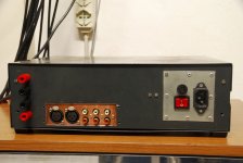
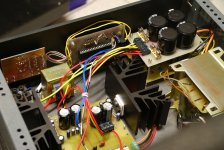
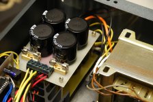
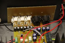
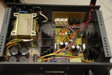
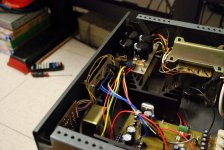
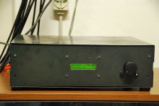
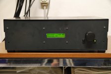
For who's interested, here are some pics of the amp.
Surely not a beauty queen, but it sounds really good in my opinion.
Surely not a beauty queen, but it sounds really good in my opinion.
Attachments
-
 DSC_0099.JPG189 KB · Views: 178
 -
 DSC_0095.JPG196.4 KB · Views: 179
 -
 DSC_0084.JPG204.7 KB · Views: 227
 -
 DSC_0081.JPG320.8 KB · Views: 227
 -
 DSC_0080.JPG281.3 KB · Views: 211
 -
 DSC_0079.JPG262.5 KB · Views: 340
 -
 DSC_0078.JPG275.5 KB · Views: 344
 -
 DSC_0071.JPG291 KB · Views: 343
 -
 DSC_0069.JPG227.9 KB · Views: 385
 -
 DSC_0100.JPG190.7 KB · Views: 155
- Home
- Amplifiers
- Chip Amps
- Blown TDA7294