Hi!
those two mistakes...¡not my case fortunately!...but maybe another one...😕
I was checking other threads also, and found what maybe a big mistake in my layout: the secondary CT of my pcb trafo is connected to the gnd plane, and as the secondary is oriented at the same side as the regulators and the "clean side" of the psu... maybe the gnd gets contaminated with secondary pulses..??
The CT must go to the first junction of the smoothing capacitors.
If there are more than 1pair then the first junction gets extended to meet the second junction.
The output to the amplifier is from the last junction.
This places the OUTPUT farthest from the CT.
If there are more than 1pair then the first junction gets extended to meet the second junction.
The output to the amplifier is from the last junction.
This places the OUTPUT farthest from the CT.
Yes. Connecting the CT to the output side of the PSU is simply another implementation of the two mistakes I listed; it injects charging pulses straight into the audio ground. Buzz is almost inevitable.
Hi!
Attached are two pictures that show part of a new psu layout. A one layer board. it shows transformer secondary conection to gnd. two versions of it.
The diode bridge shows a snubber with 4 47nf caps. and a 10nf cap entering the two AC pads.
On the picture V1(left picture) the secondary gnd conection depends on thermal pads near the area of the first filter caps
On the picture V2 (right picture) the secondary gnd connection is taken with traces to the first negative rail capacitor.( Red and yellow traces)
Another point to comment, is the unregulated rail for relays, in the v2 picture. (10R and 1000uf). As the gnd of this capacitor is connected to the plane, and consequently also to the output gnd....¿wouldn't it be responsible in part of the injected pulses into the output?....hmmm
Any comment is wellcome.
¡Thanks a lot!
JAY X
Attachments
Last edited:
Hi,
your ground should be pin 12 and 13, not 12 and 14.
2x115V PCB Mounting Toroidal Power Transformers from Nuvotem Talema
I wonder what voltages you measure at psu output?
your ground should be pin 12 and 13, not 12 and 14.
2x115V PCB Mounting Toroidal Power Transformers from Nuvotem Talema
I wonder what voltages you measure at psu output?
It's unsafe to have a fused (AC line voltage) Neutral. In the case of a failure, the Neutral fuse can blow (but not the Hot fuse) leaving the component at line voltage.
If a dual circuit breaker is used, the Hot & Neutral breakers need to be linked together, so that if one trips the other is turned off.
If a dual circuit breaker is used, the Hot & Neutral breakers need to be linked together, so that if one trips the other is turned off.
Jay is right.
Your link 12 to 14 is connecting the secondaries out of phase.
You need to swap the two traces that connect to 13 & 14.
Remove the capacitors from your secondaries. Capacitors are not snubbers.
Resistors are snubbers !!!!!
You need resistors across the pins 11 &12 and also aceoss 13 & 14.
To prevent the resistors blowing up, you then add a series capacitor to each resistor.
The combined R+C then acts as a snubber that does not blow up.
If you read quasimodo, you will discover that all this has been posted on the Forum.
This has already been said, but maybe Jay needs to be told twice ! Did you reply?It's unsafe to have a fused (AC line voltage) Neutral. In the case of a failure, the Neutral fuse can blow (but not the Hot fuse) leaving the component at line voltage..................
from post4.Fit a very high fuse rating into the Neutral side of the dual fuse IEC. You don't want the neutral fuse to blow leaving the Live fuse still powering all the live bits to 220Vac after you think the unit is apparently OFF !
Hi!
Ok!.no caps for snubbers!
With the secondaries wired like the pictures...i got -17,3v and 17,5v at output. But yes, it needs to be corrected. I will post new pictures today if possible.
My iec inlet filter has two fuses and i use a 4 pole ac switch.
Regarding the unregulated rail for relays, (resistor and cap coming from the +v side of diode bridge) would it be better to have a gnd trace up to the ouput instead of a thermal pad to gnd?
Fit a very high fuse rating into the Neutral side of the dual fuse IEC. You don't want the neutral fuse to blow leaving the Live fuse still powering all the live bits to 220Vac after you think the unit is apparently OFF !
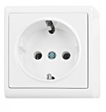
GB/US mains plugs differ from those on the european continent. Schuko plugs (so called in Germany, I think in Spain the same plugs are used) can be connected in 2 directions to the wall socket, so you never know which is neutral and live at your AC inlet.
I have not travelled much on the continent, but the few countries I have visited do have polarised sockets.
Maybe the users are buying a non polarised plug that can be fitted back to front in a polarised socket.
We have a little figure of 8 plug and socket on some of our double insulated equipment. That is intended to be non polar and can be fitted both ways around.
Maybe the users are buying a non polarised plug that can be fitted back to front in a polarised socket.
We have a little figure of 8 plug and socket on some of our double insulated equipment. That is intended to be non polar and can be fitted both ways around.
I have not travelled much on the continent, but the few countries I have visited do have polarised sockets.
Maybe the users are buying a non polarised plug that can be fitted back to front in a polarised socket.
Nope, at least not here in Croatia.
Attachments
Do the pins at top and bottom have different projections?
They should prevent a polarised plug being inserted upside down.
They should prevent a polarised plug being inserted upside down.
Do the pins at top and bottom have different projections?
They should prevent a polarised plug being inserted upside down.
They have the same projection, so you can put cable in two ways. You can even
mount the inlet upside down on the wall, so you never know which hole is hot and which hole is neutral.
Only those pins you asked about are always for protective earth. (well not quite so, in some old buildings, those PE pins are jumpered to neutral)
Last edited:
Yes, you are right, there is not only one standard on the continent, but many countries use Schuko as standard. For more information: https://en.wikipedia.org/wiki/SchukoI have not travelled much on the continent, but the few countries I have visited do have polarised sockets.
----
Schuko sockets are unpolarised, there is no way of differentiating between the two live contacts (line which is approximately 230 V to earth and neutral which is approximately 0 V to earth) unless the voltage to earth is measured prior to use.
The IEC 60906-1 standard was intended to address some of the issues in regards to polarisation and replace Schuko, but the only country to have adopted it is South Africa.
----(from the above link)
Don´t forget a voltage tester at your next trip to the continent.😉I am so happy that I live in a country that protects the innocent from "evil" sockets.
The result of your secundary configuration (12, 14 to GND) is a half wave rectifier ( with two diodes working in parallel!), that means the caps get charged only every 20ms instead of 10ms. So you get a doubled ripple voltage and therefore a lower average value at the reg. inputs. This was the reason why I asked for the measured output voltages.Hi!
With the secondaries wired like the pictures...i got -17,3v and 17,5v at output. But yes, it needs to be corrected. I will post new pictures today if possible.
Is -17,3V and 17,5V what you expected?
I would avoid rough filtered voltage for relay supply, there is a risk to introduce hum somewhere in the audio path. Well, the risk depends on for what the relays are used and the layout (signal tracks close to relay supply tracks)Regarding the unregulated rail for relays, (resistor and cap coming from the +v side of diode bridge) would it be better to have a gnd trace up to the ouput instead of a thermal pad to gnd?
Hi Andreas!
The voltages, -17,3v and 17,5v are as expected. The 0,2 volts difference in the negative rail...not much problem. thats ok.
Finally for the psu boards i already have made, i found a solution. Cut the part where the trafo sits, so i can place it in a separated board and wire it correctly.
The relays are for audio routing. They have thick gnd and power traces in the audio board, and are well spaced from audio tracks. So no problems by now!.
JAY X
Hi,
When I consider that crosstalk is mainly caused by capacitive coupling, thick traces are counterproductive.
But anyway, if your project works well it´s not a problem.
Yes, with 1% tol. resistors for the voltage adjustment at 317/337 this difference is perfectly normal.The voltages, -17,3v and 17,5v are as expected. The 0,2 volts difference in the negative rail...not much problem. thats ok.
You need not to separate the trafo, just interrupt the traces 13/14 and connect it correctly with short pieces of wire.Finally for the psu boards i already have made, i found a solution. Cut the part where the trafo sits, so i can place it in a separated board and wire it correctly.
Are the relay gnd-traces running completely separated from audio gnd back to the psu board?The relays are for audio routing. They have thick gnd and power traces in the audio board, and are well spaced from audio tracks. So no problems by now!.
When I consider that crosstalk is mainly caused by capacitive coupling, thick traces are counterproductive.
But anyway, if your project works well it´s not a problem.
- Status
- Not open for further replies.
- Home
- Amplifiers
- Power Supplies
- blown fuses in dual fuse iec inlet