I built
figure 1a
http://sound.westhost.com/project03.htm
it worked great for about 3 hours with perfect sound, low distortion, great response and then I heard a fizzle sound and the bd139 and bd140 transistors blew. I replaced them and they blow again as soon as I turn the amp on.
What could cause this? and why did it work for so long?
rtill said:
it worked great for about 3 hours with perfect sound, low distortion, great response and then I heard a fizzle sound and the bd139 and bd140 transistors blew. I replaced them and they blow again as soon as I turn the amp on.
Hi
Inspect the 220 Ohms resistors and if the output transistors 3055/2955 are not burned.
If they are burned, when you put new drivers BD139/140, they immediately burn...
PS: Inspect also the 0,22 Ohms resistors
Edit: PS...
looking at it closer, after replacing the bd139 and bd140 and firing it up, the .47 5 watt resistors cracked as well. So does this sound like the output transistors (mje3055 and mje2955) are blown?
rtill said:looking at it closer, after replacing the bd139 and bd140 and firing it up, the .47 5 watt resistors cracked as well. So does this sound like the output transistors (mje3055 and mje2955) are blown?
Yes, strong possibility, inspect them...
Mount the 1N4001 diodes on the heatsink. Better still replace them with a VBE multiplier circuit as shown in figure 1a - use a BD139 or MJE340 for the VBE transistor and make sure it's tab is bolted to the heatsink
this amplifier
is almost impossible to fail ..... whats the rail voltage ???
and also have you got original pcb or home made ???? is the caps values correct or you made something that creates some ocilation together with a bad pcb ????
this is made it hink for rails 30+30 volts max ...higher rail voltage will not possible for this amp
rail voltages are 34.7 + and -
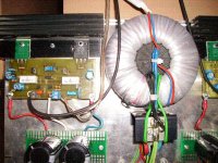
I made it on perf board and used a heatsink from a computer processor.
all 100 pf caps that it calls for, I used 150 pf, otherwise the circuit is exact. It worked great for 3 straight hours. So I would be confused of why it could only handle 30 Volts per rail.
I made it on perf board and used a heatsink from a computer processor.
all 100 pf caps that it calls for, I used 150 pf, otherwise the circuit is exact. It worked great for 3 straight hours. So I would be confused of why it could only handle 30 Volts per rail.
well ....
34.5 is not much but cooler of a procesor from a pc might not be enough ....
meaning that if you have just a bit toomuch idle .....then all thing gets too warm and then boom .... put a decent heatsink allow proper insulation be tween transistors and then all will be fine ....
you might consider going to project 3 a that has ajustable idle
will work like hell and also plays very fine
IMPORTAND
on vas amplifier bd139 there is capacitor that should remain 100 pf ..... 150pf will have alot of effect in the quality of sound .....
about the second driver bd140 this change of 50pf more i dont know what really effects
also in a version i made 100mf decoupling caps are located very next to the power transistors conected to rails and ground ..... very nice improovement also
Attachments
An obvious question, and one that no one has posed so far, is: Where did you buy the output transistors, and is there a possibility that they are counterfeit?
'Work for a while and suddenly go "BOOM"' is a common symptom of getting bitten by counterfeit devices.
'Work for a while and suddenly go "BOOM"' is a common symptom of getting bitten by counterfeit devices.
i ve said ....
in the past about these transistors .....
they where imported to greece n very nice original boxes arround the year 1992 ..
order was placed to toshiba with very strickt specs for a special audio amp made in greece
he he he but then the company just shut down cause one of the two brothers dicided to do something else ....
so i bought them for nothing !!!!! i have now more than 200 n and 200 p and not only they are original but also have matching coding on them by the factory so all there specs are the same with a tollerance of 15 % many times checked so far
of course there is no chance i am selling even one of them .....i prefer to sell my hand !!!!!
best regards .... a happy 2sa1302 and 2sc3281 owner
funny story to read
the person who wanted to design this "special amp "....made of course a terrible mistake .....
the amplifier previously produced by this company was a very simple amp 35w about with 2x2N3055 ( talking about the 80's) with all the goodies like ccs vbem with abc 549 mounted on heatsink....so this was a modular pcb fited in amplifier box with a 5 slot module case and common psu and all the proper controls for a 5 zone 100v amplifier used for hotels or hospitals and goes on .....
the truth is that it was a very special design called xenia 550 that had amazing for the 80"s functions ....like multizone ( you can choose from three sources what to play for every zone ) local monitor ....interconnect with a fire alarm paging mikrofone and also by pass function to bypass the music and make emergency anouncement in case evacuation needed ....
troully sofisticated many of them produced ( even now days you may find simular things but nothing that include all this ) and most of them working like hell
some of them failed there was this designer called in to design another module that will never fail .....so this guy :
designed one amp that still produces 35w but uses 2pcs of 2sa1302 and 22sc3208 !!!!!!! TO PRODUCE 35W !!!!!!!
MEGA JOKE !!!! thank god he never manged to put in production and then i got to get the transistors .....
the ruth was that even original amplifier had all shorts of protection there was one point that couldnt be protected and that caused the fail on the amps
thermal protection was there dc also overdrive also everything except one :
if during the installation signal of zone one was mixed with zone two and so on then this as audio signal could not be detected by any unit resulting amplifier of zone 2 be a load to amplifier of zone one ....result a slow death ..... slow but death .....
so fail was due to instalation and not on production of the amp .....
but thats just a history .....
General comments
From my experience and after a looking in the amp. schematic, i have two remarks. The first it is that, this amp. has a CFP type output stage. The other type - and most commonly used - it is the EF output. In comparisson between them, the CFP appeared as some better in frequency response but it is also most delicate from the EF which is by far most rugged. Also in class AB the CFP output produces more heat than EF in iddle state thus it needs bigger heatsinks. A concrect drawback of CFP it is that, if the output transistor blocked i.e. under a saturation condition, then all the output current pass through the smallest driver to the load and then it destroyed. You can make as i think an easy experiment to convert the output in EF. Leave as they are the drivers, move the 220Ù resistors between the emitters of BDs and the output rail, connect the collectors of BDs in supply rails, interchange the output transistors between them (3055 in +supply rail and 2955 in -rail) disconnect the base of each output transistor from the collector of each driver and reconnect it in the emiter of the driver. Leave the collector of each output transistor connected in supply rails directly. Thus you can obtain a EF arrangement in output. Try it and make a comparison in ruggedness and the sound quality. One more remark, it is the absence at least of the output clamping diodes which protect the output devices from the unwanted returned currents from the load to the output transistors during the opposite cycle of output swing, which can apply a peak voltage of 70V (in your case with the +/-35V supply level) accross the c-e contacts of the inactive transistor during this momment and don't forget that although 3055-2955 has a Ic=16A their Vce it is only 60V. Place two 1N4004 (for certainity) each one accross the output rail and each one of the supply rails in a reverse connection. Be carefull to include also the emitter resistors into!
I think you resolve your problem with this modification.
Fotios
fotios .....
very nice comments indeed .....
i will add mine also
this amplifier i constructed for fun bud not exactly the 03 but the 03a..... including a vbem with the transistor bc 549....
created a nice pcb added 0.1mf +100mf very next to output transistors also used 42+42 rails idle about 120ma and banks of 2*10.000 mfd per amplifier board .....outputs with the very original 2SA1302+2SC3281
i repeat ..this amp i ve made for fun BUT !!!!!! since in my shop there is short of parade of amplifiers meaning that every day one yamaha or one sansui or one akai comes in for repair ...of course all of them simple amplifiers some of them made in the 80's but most of them made with simular techonologies.....
well this litle skatoulaki will outperform all of these for nothing ......its very obvious the clear high very strong but controlable bass and present but not overeacting midle ...
the funny thing is that i listen to this amp for more than 2 month every day now with the same cd and same speakers and also had the chance to compaire with almost 20-30 amps ....big and small integrated or line amps ..... most of them outperformed in quality ...as about power really dont know ....
i dont evenknow my amplifier how much power does it make ...didnt bother to see
there is no question of reference ....you can simply hear it espacially in high most of amps comapired to this is "hassy" and confusing .....
thats it
sakoulis
Re: fotios .....
Hello Sakoulis
Fotoulis
sakis said:very nice comments indeed .....
i will add mine also
this amplifier i constructed for fun bud not exactly the 03 but the 03a..... including a vbem with the transistor bc 549....
created a nice pcb added 0.1mf +100mf very next to output transistors also used 42+42 rails idle about 120ma and banks of 2*10.000 mfd per amplifier board .....outputs with the very original 2SA1302+2SC3281
i repeat ..this amp i ve made for fun BUT !!!!!! since in my shop there is short of parade of amplifiers meaning that every day one yamaha or one sansui or one akai comes in for repair ...of course all of them simple amplifiers some of them made in the 80's but most of them made with simular techonologies.....
well this litle skatoulaki will outperform all of these for nothing ......its very obvious the clear high very strong but controlable bass and present but not overeacting midle ...
the funny thing is that i listen to this amp for more than 2 month every day now with the same cd and same speakers and also had the chance to compaire with almost 20-30 amps ....big and small integrated or line amps ..... most of them outperformed in quality ...as about power really dont know ....
i dont evenknow my amplifier how much power does it make ...didnt bother to see
there is no question of reference ....you can simply hear it espacially in high most of amps comapired to this is "hassy" and confusing .....
thats it
sakoulis
Hello Sakoulis
Fotoulis
fotios
mooved away from mosfets .....
construct bjt again
construct for a bit more quality
construct for less power
construct with more safety
construct generally
mooved away from mosfets .....
construct bjt again
construct for a bit more quality
construct for less power
construct with more safety
construct generally
Found the problem.....
I need a bigger heatsink. O/P transistors got too hot, melted the mount kit, shorted the transistors and blew them.
I need a bigger heatsink. O/P transistors got too hot, melted the mount kit, shorted the transistors and blew them.
- Status
- Not open for further replies.
- Home
- Amplifiers
- Solid State
- blowing transistors