Shone the light from the back of the board. Do you see any 'shadows' in the fiberglass around any of the pads, in that area?
If the light won't shine through metal, it's not 'bright'.
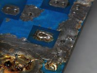
I'm looking for contamination of the board. When there is electrolyte that has saturated the board, there is usually a sort of shadow. I don't see it in your boards.
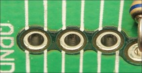
I am, however, concerned that the vias are damaged. The top solder pads have an adjacent hole (via) on top of the board, clean that out and insert a piece of wire that will solder onto the top and bottom of the board to ensure that there is a solid electrical connection between the solder on the lead on the bottom of the board and the top pad on the board.
It will look something like the attached image on the top and bottom of the board.
I'm looking for contamination of the board. When there is electrolyte that has saturated the board, there is usually a sort of shadow. I don't see it in your boards.
I am, however, concerned that the vias are damaged. The top solder pads have an adjacent hole (via) on top of the board, clean that out and insert a piece of wire that will solder onto the top and bottom of the board to ensure that there is a solid electrical connection between the solder on the lead on the bottom of the board and the top pad on the board.
It will look something like the attached image on the top and bottom of the board.
Attachments
The only vias that would have been impacted are the holes for the component itself. When I solder the new one in, that should connect the two layers.
OK, thanks for the tip. I will make sure they are electrically connected when I install the new parts.
When you get the replacement caps, you may want to install one across the + and - 12v power connections, clamp all transistor to the heatsink and power up the amp. Let it idle for at least 10 minutes. Do you see any heating around where the leaking caps were located?
Great idea. I'll do that.When you get the replacement caps, you may want to install one across the + and - 12v power connections, clamp all transistor to the heatsink and power up the amp. Let it idle for at least 10 minutes. Do you see any heating around where the leaking caps were located?
I did put the OHM meter across the 12V input (where the capacitors would have been) and it was very high. Don't recall the number though.
Have not ordered the parts yet- Waiting a bit until I need some other things. Shipping from the part suppliers is expensive, and not sure I trust Amazon sellers. Too much counterfeit stuff on there.
Thanks
I got this amplifier working again back when this thread was new... But for the 2nd summer, I am having issues with it cutting out (overheating). Other than that, it sounds amazing!
Any advice on why it is overheating (only when it is hot out)?
Thanks
Any advice on why it is overheating (only when it is hot out)?
Thanks
I know nothing about the series 8. Does it have the multi-stage rail supply? If so, is it switching from low to high, as it should?
Did you think about adding a fan blowing over the heatsink if the rails are switching?
Is the bias holding steady at high temps?
Did you think about adding a fan blowing over the heatsink if the rails are switching?
Is the bias holding steady at high temps?
Last edited:
Not sure if it has multi-stage rail supply. It is installed in the car right now, how would I know?
I guess I should have also mentioned I only have this problem when it is playing at higher volume. If I keep the volume low, there is no problem.
Yes, I considered a fan or some other method of external cooling- but was concerned that maybe something else was wrong for it to be getting that hot to begin with?
MOER would know for certain.
Does it have vari-power on it anywhere?
The reason I asked about the bias because the replacement output transistors may not perfectly match the originals and the bias settings may have to be different. You would have to check idle current hot and cold to know if it's holding.
Does it have vari-power on it anywhere?
The reason I asked about the bias because the replacement output transistors may not perfectly match the originals and the bias settings may have to be different. You would have to check idle current hot and cold to know if it's holding.
It sounded to me like the "bias settings may have to be different" was something I'd have to test and adjust for.
The first thing I'd recommend is finding the idle current at cold and hot temperatures to see what they are and if they remain the same (hot and cold).
Do you have a signal generator and a scope?
Do you have a signal generator and a scope?
- Home
- General Interest
- Car Audio
- Blowing the dust off my Hifonics Boltar VIII