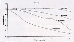
"If you want to run in 4 ohm , replace with Sanken 2SC3264/2SA1295 and blow cold air on heatsik with one PC fan. " While a fan is a good idea the 2SC3264 is not. http://www.allegromicro.com/skncatlg/pwrxtr/2sc3264.pdf From the spec sheet we can see that the 2SC3264 is: 1)the wrong case style 2)plastic, with a maximum temperature of 150*C 3)has less safe area than the MJ21194. The MJ21194 is a 250W part, the 2SC3264 only 200W.At high voltage the safe area is greater on the MJ21194.With a small heatsink and only a few outputs the temperature will be quite high.With a junction temperature of 100*C the 2SC3264 can only handle 60W because it derates to zero at only 150*C.At 100*C the MJ21194 can handle 150W because it derates to zero at 200*C. With +/- 75V and an 800VA transformer this amp will do 400W at 4R.In class AB it will need to ge rid of 160W of heat, 40W per output device.If that sink was 0.5*C/W (fat chance of this) then the transistors will be 80*C above ambient, ie 105*C.Under these conditions the metal cased MJ21194 will handle 250% more power than the plastic cased 2SC3264.Did I mention that the current gain begins to droop on the 2SC3264 above 4A? The MJ21194 is good out to 10A .400W at 4R is 7A per device.The 2SC3264 would be marginal at best in this design.
I'm not an amp designer and my electronics experience is limited, so I can only go by what others tell me until I can get more theory under my belt. But seeing the schematic that I posted, is there anyway to get this amp to run off of +-75 Volts or should I just lower the voltage down. Assuming that I can get it to run off of +-75 V, what changes need to be made to the circuit, and what parts need to be swapped out to produce a reliable amplifier that can run 4ohms continuously and without blowing itself up when it clips?
I have several of these kits that I have put together and would like to be able to use them witout worry of frying the amps and what ever is connected. I know about protection circuits and have some for these amps to disconnect when the output goes DC, but having a fool proof amp would be very nice.
I have several of these kits that I have put together and would like to be able to use them witout worry of frying the amps and what ever is connected. I know about protection circuits and have some for these amps to disconnect when the output goes DC, but having a fool proof amp would be very nice.
DJK ,
Look with more attention to datasheet for both tranzistors !
2SC3264 have SOA at 80V - 2.5A on DC , and 8A Peak
MJ21193 have SOA at 80V - 2.5A at 1 second, single puls
If want to see an amplifier with 2sc3264/2sa1295 take a look to SWR SM-900. With only 2 Pair on channel it can run 450w/2ohm and it have just one 12v PC fan. But is not all. If it run in 4 ohm mode the fan run time to time becouse the amplifier have termic regulator ( 50 centigrade Celsius ).
I have one SWR amplifier (made in USA ) from 3 years and I don't have any trouble.
I like very much MJ21193 , but it have smaller contact area .
2SC3264 in MT200 case have 6,5 square centimeter with 25-30% more TO3 .
DJK , on paper ( read datasheet ) everything is like you say, but in real world diference can give other balace . I think you see , I don't say anything about Hfe , Ft .
Read more from http://www.geocities.com/ResearchTriangle/8231/tra/
Attachments
DJK,
I have to strongly object your view tat a transistor coming out of Hong Kong is counterfeit. Note that I do agree that at +/-75V rails, it's probably out of the SOA for the MJ15003/4.
On the issue of counterfeit, I understand there have been a lot of grievance from parts purchased in the Asia pacific region, but it does not indicate anything coming out from HK is counterfeit. I have purchased kits from these people before and I have no problem with mine.
In fact, if you own a PDA, the DragonBall series processors are designed developed and manufactured in Hong Kong. Are they counterfeit? Probably not.
I am going with a lower supply voltage, the output of the amps will still meet my requirements easily. What should I set the quescient current to though. If I am running with +-38V rail or so, would I keep the quescient current the same or would I need to change it?
Thanks guys. It's good to know that there is a decent sized DIY community out there who is willing to help others. For the longest time I have not had the convenience of being able to ask others of how to do something. This board definately gets 5 stars from me.
Thanks guys. It's good to know that there is a decent sized DIY community out there who is willing to help others. For the longest time I have not had the convenience of being able to ask others of how to do something. This board definately gets 5 stars from me.
"I have to strongly object your view tat a transistor coming out of Hong Kong is counterfeit.On the issue of counterfeit, I understand there have been a lot of grievance from parts purchased in the Asia pacific region, but it does not indicate anything coming out from HK is counterfeit. " I stand corrected.The countefeit parts I received came from DALBANI, a firm based in the mid-east with outlets in Florida (USA) and London (UK).Other mechanical parts; jacks, binding posts, speaker stands, and hand tools; were of such low quality that I have vowed never to buy anything from them again.I should have been more specific the first time.Sorry.
"Note that I do agree that at +/-75V rails, it's probably out of the SOA for the MJ15003/4. I have purchased kits from these people before and I have no problem with mine." I had a love-hate relationship with Mark V.They come so close to delivering a good product, and then fail.The design of this 300W(TA-3600) amp is a good example.I have also done their stereo 80W units(TA-802) , the stereo 120W unit(TA-800 MK2)and the LED display (TY-45).I designed and built several dozen 300W and 600W subwoofer amplifiers in their rack mount cases.They offer very good value for their heatsinks, cases, transformers, and circuit boards(the quality of the work, not the design of the circuit).Their circuit designs leave something to be desired.
"Note that I do agree that at +/-75V rails, it's probably out of the SOA for the MJ15003/4. I have purchased kits from these people before and I have no problem with mine." I had a love-hate relationship with Mark V.They come so close to delivering a good product, and then fail.The design of this 300W(TA-3600) amp is a good example.I have also done their stereo 80W units(TA-802) , the stereo 120W unit(TA-800 MK2)and the LED display (TY-45).I designed and built several dozen 300W and 600W subwoofer amplifiers in their rack mount cases.They offer very good value for their heatsinks, cases, transformers, and circuit boards(the quality of the work, not the design of the circuit).Their circuit designs leave something to be desired.
"Look with more attention to datasheet for both tranzistors !
2SC3264 have SOA at 80V - 2.5A on DC , and 8A Peak
MJ21193 have SOA at 80V - 2.5A at 1 second, single puls
If want to see an amplifier with 2sc3264/2sa1295 take a look to SWR SM-900. With only 2 Pair on channel it can run 450w/2ohm and it have just one 12v PC fan. But is not all. If it run in 4 ohm mode the fan run time to time becouse the amplifier have termic regulator ( 50 centigrade Celsius ).
I have one SWR amplifier (made in USA ) from 3 years and I don't have any trouble.
I like very much MJ21193 , but it have smaller contact area .
2SC3264 in MT200 case have 6,5 square centimeter with 25-30% more TO3 .
DJK , on paper ( read datasheet ) everything is like you say, but in real world diference can give other balace . I think you see , I don't say anything about Hfe , Ft . "
Is this a contest to see who can design the worst amplifier? Even then it takes someone very knowledgeable to design a cheap piece of junk that will hang together long enough to make it through the (short) warranty period. I've been there and done that. And it leaves you with a bad taste in your mouth even as it puts a bunch of money in your bank account.While the 2SC3264 has the same safe area at 80V at room temperature, the MJ21194 has 25% more safe area at 50V and 100V which corresponds to worst case normal operation(half rail voltage) for an amp like the QSC USA1310 with its +/-93V rails and worst case fault operation (full rail from shorted load).But what you really failed to comprehend is derating due to temperature. Because of the thermal resistance from the junction to the case and the case to the heatsink the junction can be at 100*C, the boiling point of water, and the heatsink only warm to the touch.At 100*C temperature the 2SC3264 can only handle 60W vs the MJ21194 150W, as I explained before.That means that even though the data sheet shows the safe area to be the same on both parts at 80V at room temperature, in a real amplifier under real operating conditions, the MJ21194 will handle 250% more power. The issue here is metal vs plastic, the MJ21194 is also available in plastic,the MJL21194.In the plastic case it has exactly the same poor power rating as the 2SC3264 does.DIY is about quality and learning.There is no way you can build an amplifier for less money than what a used QSC, Crown, or Peavey sell for.
There is a way that you can use your MJ15003/MJ15004 transistors and still use +/-75V rails. With a little modification, you can put the output devices of your amp in series/parallel so each will only see half the total supply voltage. So you can see how it's done, here is a link to plans for an amp that's like this, the Leach Superamp. It has two MJ15003/4 in series and two in parallel for each side. It can run with up to +/-93V rails. High enough?
http://users.ece.gatech.edu/~mleach/superamp/
http://users.ece.gatech.edu/~mleach/superamp/
"With a little modification" Like about 15~20 more parts? Cut a bunch of traces and hang the extra parts in mid air? Thanks, we needed some comic relief.
The Leach SuperAmp isn't that much different from the Leach Amp, there's only a few extra parts, and there is such a thing as breadboard that you can mount above or below the main board, but I must admit that I probably wouldn't try it. It can probably be done though. Just a thought.🙂
"there's only a few extra parts" Uhh Kilowatt, I've done this before.I took a Pass A40 driver board, re-designed it to run on +/-80V and used it to replace the missing driver board in an SAE 2400 (which has series connected outputs just like the Super Leach).Sure it can be done.But the guy that can do it won't have to ask any questions here.
"the guy that can do it won't have to ask any questions here" Well, technically, almost anyone with some knowledge of OPS design could do it. I could do it, but I guess the key word here is "COULD". Anyway, I won't argue, I'll take your word that it wouldn't be worth it. I'm sure it's very hard.
Forget the +-75V rails for now, what do I need to set the quiescent current at when running at another voltage. Do I still keep it at 75ma? what happens if I set it higher or lower?
If you run at 1/2 original voltage, you can go up to 2 times the idle current. That should lower distortion, especially the cross-over type.
Jeremy_Wolf said:I'm brand new here so I thought I would give a little background info.
Some of you may remember the company Mark V electronics that sold amplifier kits, the guy who ran the company closed up shop, but before he did he let everyone know who his supplier was. That company was Sound Master International out of Hong Kong, web address:
http://www.hkiol.org/template/0001/template.htm
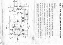
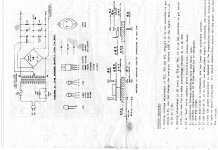
A while ago I ordered some of the 300W Amp kits and built them. They worked great if I used a low power supply voltage such as +- 40V DC, if I hooked up a low impedence load such as 4 ohms and got clipping, everything was ok physically (except the produced sound, yuk). However, if I upped the voltage to the recomended +-75V, when I would get clipping I would lose half of the power transistors usually, as well as the op amp in the pre amp stage. For the life of me, I can't come up with a solution since my electronics background is limited to hobbiest activities. I can troubleshoot and repair the amps, but I would prefer to be able to drive them closer to their rated outputs to get more power from them. I tried replacing the output transistors with MJ15003's but still had the same problem.
I can post the schematic for these amps if anyone can help me troubleshoot them.
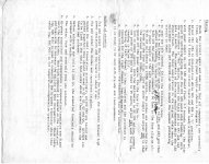
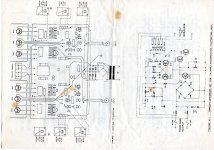
Here are the schematics and the instruction manual as well.
I'm glad that I found this forum, what a great way to get some more electronics experience.
http://www.lvcm.com/zombiess/amp/circuit.gif
http://www.lvcm.com/zombiess/amp/parts_list.gif
http://www.lvcm.com/zombiess/amp/powersupply.gif
http://www.lvcm.com/zombiess/amp/page1.gif
http://www.lvcm.com/zombiess/amp/page2.gif
http://www.lvcm.com/zombiess/amp/page4.gif
http://www.lvcm.com/zombiess/amp/page5.gif
http://www.lvcm.com/zombiess/amp/page6.gif
Today these links don't work anymore 🙁
I search only the schematics...
sound master amlifier
hey i have a sound master VF200 and if i meseuer the voltage on my right channel i will get around 14-16 volts with load on it, but when i meseuer the voltage on my left channel i will onli get around 9 volts with load and i'm not sure why? can any body help me or can any body tell me weather rs do a J50 or a K135 replacement or equivelent ? plz plz can you help me
many thanks Cerwinvega (josh) 😕
hey i have a sound master VF200 and if i meseuer the voltage on my right channel i will get around 14-16 volts with load on it, but when i meseuer the voltage on my left channel i will onli get around 9 volts with load and i'm not sure why?
can any body help me or can any body tell me weather rs do a J50 or a K135 replacement or equivelent ? plz plz can you help me many thanks Cerwinvega (josh) 😕
Hi,
I was digging in the junk box and found this TA-802 amp it was still complete and the transformer was still wired up.I said why not see if it will run,I looked on the net for some info,because I have moved alot lately and wasn't sure where I would find the docs on it,but I scanned them and will put them up,for anyone that needs them! It ran fine ,I did reform the 10,000uf caps but that was all !
😀😀😀
NS
Attachments
Nelson, I have tried the diode thing before, but when I was checking them with my scope and inputting a sinewave, i noticed that the output was being shaped by the diodes above about .8 volts with two of them in series. I have tried multiple types of diodes and all give a similar response. Is there a better way to do it with an op amp where it will just limit the overal signal. I guess a compressor would sort of do this, but I want the full dynamic range, just not to go above a pre-set level.
I always add two 12V zeners counter series between the input and GND (12.7v swing max either direction) to protect inputs but not to limit them, because of the very thing you mentioned. To have signals with a 1V rms pass through unaffected it wasn't untill I started to use zeners of over 8V.
You could try the output diode clamps to eat up induced overvoltage that's been suggested.
- Status
- Not open for further replies.
- Home
- Amplifiers
- Solid State
- Blowing ouput transistors when clipping, why?