http://www.diyaudio.com/forums/atta...5113702-blh-example-hornresp-pictures-hr6-jpg
Note that a TL, horn made with parallel panels and flat divider boards is a parabolic expansion, so [con] needs to be changed to [par] by double clicking on them.
GM
Note that a TL, horn made with parallel panels and flat divider boards is a parabolic expansion, so [con] needs to be changed to [par] by double clicking on them.
GM
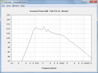
Here is what you get.
Hi dhenryp,
You are using an old version of Hornresp. The latest release will give you a more accurate prediction of the combined power response - see attachment.
Kind regards,
David
Attachments
what is CC size ?
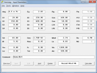
The throat chamber volume Vtc expressed in cubic centimetres (cc).
The Vtc value used in the example is 1300 cc.
The Atc value used in the example is 100 sq cm.
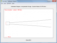
When I also got the schematic diagram it shows a rear enclosure volume of 0.9l can you confirm this with yours?
The schematic diagram should look like attachment 1 and the input parameter values should look like attachment 2.
Attachments
David
Approximately how close will the simulated response be with respect to the measured response for the direct radiator part of the combined response? Is there a fudge factor one can apply? Thanks.
Thanks for the tool.
SMathews
Approximately how close will the simulated response be with respect to the measured response for the direct radiator part of the combined response? Is there a fudge factor one can apply? Thanks.
Thanks for the tool.
SMathews
Hi SMathews,
Assuming that all the input parameter values are correctly specified, the predicted direct radiator power response should be reasonably close for those frequencies where the driver diaphragm is acting as a rigid piston (Hornresp models the driver diaphragm as a rigid plane circular piston). If required, the Directivity tool can be used get an idea of the likely pressure response. Cone break-up resonance mode effects at higher frequencies are not taken into account in the Hornresp simulation models.
I am not aware of any fudge factors that can be applied to make the power or the pressure response predictions more accurate (the lossy inductance model which is sometimes used with large voice-coil drivers, was derived empirically from experimental data).
Not a problem 🙂.
Kind regards,
David
Approximately how close will the simulated response be with respect to the measured response for the direct radiator part of the combined response?
Assuming that all the input parameter values are correctly specified, the predicted direct radiator power response should be reasonably close for those frequencies where the driver diaphragm is acting as a rigid piston (Hornresp models the driver diaphragm as a rigid plane circular piston). If required, the Directivity tool can be used get an idea of the likely pressure response. Cone break-up resonance mode effects at higher frequencies are not taken into account in the Hornresp simulation models.
Is there a fudge factor one can apply?
I am not aware of any fudge factors that can be applied to make the power or the pressure response predictions more accurate (the lossy inductance model which is sometimes used with large voice-coil drivers, was derived empirically from experimental data).
Thanks for the tool.
Not a problem 🙂.
Kind regards,
David
Next define the horn expansion as two stacked conical (i.e. straight sided) segments.
My question: how to define the sizes for the horn ?
( I have an intention for the size but how to know which is good size for certain driver ? )
Jesse
Attachments
Next define the horn expansion as two stacked conical (i.e. straight sided) segments.
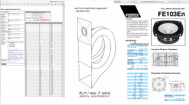
how do you find out S1 and S2 values?
- Status
- Not open for further replies.
- Home
- Loudspeakers
- Full Range
- BLH example with Hornresp in pictures