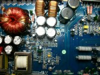
For the last two days i have been trying to repair this 4 channel amp.
When i opened the cover i found out that someone has tried to repair the amp before me.
Many SMD components were re-soldered in a bad way.....
Anyway, the amp wouldn't power up so i used my lab power supply to power the secondary side (the audio channels).
All 4 channels did not draw excessive current but one of them had 30VDC on the output.
After repairing, i looked the preamp section that tested just fine.
So far, all seemed OK, except for the PWM.
Whenever i tried to power it up, the amp got started but only for a second-no excessive current drawn...just about 1.5A.
It uses the TL494 chip and i noticed that pin4 which is designated for dead time control (and maybe for protection sometimes), after one second measures 5V.So thats the cause that the amp shuts down.
I think that if i disconnect pin4 from the circuit and ground it, it will work.
If some member could produce a schematic, i could repair the amp without canceling the protection scheme.
Do you have any DC on any channel as the amp tries to power up?
Remember to check the bridging terminals, the non-bridging terminals are likely ground.
Did you have any open or out-of-tolerance emitter resistors?
Remember to check the bridging terminals, the non-bridging terminals are likely ground.
Did you have any open or out-of-tolerance emitter resistors?
All 4 channels are working properly. DC offset is below 50mV. Output voltage without a load is 13.6VAC before clipping (due to supply voltage limit). I cannot make power measurment as i am using a Hameg bench power supply with current limit at 0.5A per rail.
Idle current for all channels is around 50mA per rail. The amps have a fixed idle current sensed by a transistor between the Sanken power transistors.
As a ground, i use the ground plane between secondary snap capacitors.
With my oscilloscope (that also displays frequency), i can momentarily measure 38.6KHz pulses to the gates of the IRF3205s.
Output voltage of the PWM power supply is +/-31VDC but as the PWM shuts down this voltage decreases slowly.
Now, i noticed something really strange:
When i power the amp from my 13.5V/68A SMPS, it shuts down really fast.
But when i powered it from the Hameg power supply (current limited at 0.5A),
the amp stays on longer (4-5 seconds) before shutting down. So when 13.5V are current limited to 0.5A, the amp stays on LONGER.
That is how i measured voltage present at pin4 of 494-it starts around 0,3V and grows up to 4.95. Then the PWM shuts down.
I did not have any out-of-tolerance emitter resistors. Two 0.22R/2W resistors are used in parallel per power transistor.
The reason one channel had DC on its output was a bad soldering to the driver transistor. I did not replace any parts in the audio section.
The reason one channel had DC on its output was a bad soldering to the driver transistor. I did not replace any parts in the audio section.
Pin 4 of TL494 is connected through a 47uF/16v and a 47K to Gnd.
It is also connected through a 4R7 to the collector of a transistor and then to another one, with several resistors around. This whole circuit ends up in a thermistor mounted on the heatsink. Although the component measures OK (12K cold), it seems that some parts are faulty and give a false alarm to the 494. This makes sense because voltage of pin 4 TL494 increased slowly up to 4.95V, forcing the Ic to have infinite dead time. And maybe thats the reason why the amp stayed on for 4-5 seconds.
What i did, was to simply remove the 4R7 and i cancel the entire thermal protection circuitry. Then i installed a Normally Open thermal switch cutting off at 75 Celsius. Now the amp works OK even with some modification.
Thank you very much Perry for your help.
You may have disabled the over-current and DC offset protection as well. If the transistor that's connected to the 4.7 ohm resistor has its emitter tied to pin 14 of the 494, remove it and restore the other circuit back to normal. If the amp powers up, reinstall that transistor. Check the transistors that are in parallel with the emitter resistors (those used for the over-current protection). Pull them one at a time to see if one in particular is causing the amp to shut down.
The transistor connected to the 4R7, does not have its emitter connected to pin 14 of TL494.
I will check the transistors you mention that are in parallel with the emitter resistors and get back to you
I will check the transistors you mention that are in parallel with the emitter resistors and get back to you
Success !!! The transistor that senses the output current of the channel that had DC on its output was shorted giving a false alarm. I just replaced it and the amp powers up just fine. Its a bit strange to me though, that it takes a few seconds for the protection circuit to shut down the amp in case of a short etc...maybe this delay is to give some "margin" to the amp...
Anyway, now i have managed to repair the amp and save the protection circuitry as well.
Excellent repair-thank you so much Perry!
Anyway, now i have managed to repair the amp and save the protection circuitry as well.
Excellent repair-thank you so much Perry!
- Status
- Not open for further replies.
- Home
- General Interest
- Car Audio
- BLAUPUNKT VA4100 schematic needed