Rick, the thermistor is the original -9400 design. I haven't modified the drivers, outputs, nor the bias spreader or thermal compensation. I don't even know if the thermal element is technically a thermistor or something else. The service manual doesn't identify it. I'm using the original PCBs. They use a card-edge connector. You can work on one channel and listen to the other. It is a pleasure to work on this one, everything's easy to get at.
Ian, thank you for drawing my attention to the limitations of capacitor bootstrapping. I got fooled at first. There's a subtlety here. With capacitor bootstrapping, the ideal bias current for the output stage is something like 75mA. If you substitute a real current-source load for the VAS, and don't alter the 75mA bias current, the amp makes almost the same amount of distortion. It was easy to conclude that capacitor bootstrapping is almost as good as a current source.
Controlling the bias current at 75mA is the mistake here. With a current source load for the VAS, the ideal bias current for the outputs is much lower, 35mA or 40mA or so. Then the distortion floor drops to 102db below signal, which is a far better result than earlier. That's on the same 19kHz + 20kHz IMD test into 4 ohms load, with output signal level peaking at +/- 3V.
Why is the higher bias better for capacitor bootstrapping? I guess it helps the gain of the output stage to approach unity, that would make the capacitor look like a higher impedance to the VAS. The same elevated bias causes the output stage to create a lot more distortion than it's capable of. The 75mA "optimum" isn't.
It's so easy to forget to control for some variable and reach a totally wrong conclusion... it's fun to learn about this stuff.
current source load for VAS and input stage
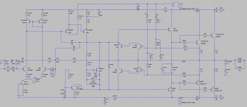
Here's an improved schematic with current sources for the VAS and input stage.
The "Jcrd" JFET and "Rcrd" resistor represent a 4.5mA current-regulator diode. Due to space constraints on the PCB, it's easier to replace a jumper with a CRD than to fit another BJT and resistor. I'll leave the existing 3.3k resistor in series with the CRD to reduce the CRD's power dissipation.
Everything else can be made to fit in the space made available by the removal of Ce6, Re9, Re10, De1, Re6, and Ce3. It's going to require cutting a couple of traces and drilling a couple of new through-holes. It can be done with a minimum of point-to-point wiring, most pins will solder direct to the PCB.
I plan to reduce VAS bias current to about 4.5mA or 5mA, from the original value of 8mA. This reduces power dissipation in Qcur1 and Qe4 to a quarter watt so they should be OK without heatsinks. There's not a lot of room for heatsinks. I haven't found a reason not to reduce bias current...
Unlike the prior design, simulation of this design shows more distortion with a large signal (peaking at +/- 40V) than with the small signal (+/-3V) on the 19kHz+20kHz IMD test. Distortion floor is 102db below signal for the small signal, 91db below signal for the large signal.
Attachments
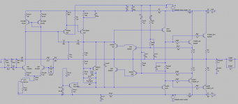
Here's another improved schematic. Now the noise and distortion floor falls to 110db below signal or better.
This borrows the compensation scheme from the Honey Badger. I don't know who came up with this topology or if it has a name. It's an excellent topology: simple, stable, and allows for vanishingly low distortion.
At audio-band frequencies, C3 is the Miller cap, being fed current through R13 from the output stage. This allows the Miller cap to linearize the output stage, even before global NFB is applied.
At high frequencies, the impedance of C3 and C4 fall with respect to R13. Now C3 and C4 together act like the miller cap, and the feedback loop shrinks to no longer include the output stage. That happens before the output stage becomes too slow to jeopardize the stability of the loop.
At middle frequencies, both Miller loops operate in tandem. There are no crazy frequency response peaks or wild phase swings on any node while the larger Miller loop phases out and the smaller one phases in, the crossover is very smooth.
A really beautiful thing about this design is that it's less sensitive to the bias current at the outputs than most class AB amps. The Miller cap will linearize the output stage even if the bias current drifts quite a bit, so performance degrades very gently with bias drift. Whereas the more conventional design from the previous post can behave very differently with 38mA or bias versus 44mA...
The only other change here is Ce4 increased from 47u to 220u to reject more of the ripple on the negative rail. And it's bypassed by a fast 1u cap. Without this change, supply noise stood out above the distortion floor.
Attachments
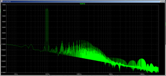
This FFT shows 9kHz+10kHz tones with all harmonics >110db quieter, for the schematic in the previous post.
The peak at 2kHz is ripple from the positive rail; the peak at 3kHz is ripple from the negative rail; everything else is distortion products.
The peak at 2kHz is ripple from the positive rail; the peak at 3kHz is ripple from the negative rail; everything else is distortion products.
Attachments
This borrows the compensation scheme from the Honey Badger. I don't know who came up with this topology or if it has a name.
It's transitional miller compensation (TMC) invented by Baxandall and Cherry.
Chapter 9 section 5 in the Cordell book.
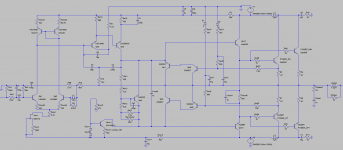
This is now built and running. There were a few late changes to the design:
- Qe3's collector resistor is reduced from 15k to 3.7k. This allows the amp to run on a variac at 1/4 normal voltage.
- Qe3 is changed from a 2n3904 to a KSC1845. The '3904 doesn't have a high enough Vce rating to work with the smaller collector resistor.
- Qe3 has a new 10p base-to-collector capacitor to prevent it from oscillating.
- Emitter resistor of Qe4 is changed from 168R to 162R, a standard value.
- The filter caps on the negative rail were formerly a 47u electrolytic bypassed with a .47u film cap. Spice sims showed most supply noise leaked in from the negative rail, so now there's a 220u electrolytic bypassed with a 1u MLCC.
The changes don't affect performance, Spice still shows a distortion floor >120db below signal in the audio band.
If I had this to do over again I'd use a 4.5mA current regulator diode in place of Qcur1. That simulates just as well, and it would have required fewer changes to the PCB. (There's already a 4.5mA current regulator diode working well for the input stage, represented by Jcrd and Rcrd on the schematic.)
Attachments
this will be the definition of the word "killjoy"
East electronics repairs now days 1000 audio devices per year ...60-70% of them is vintage amplifiers ...
The above is said in an attempt to convince that i know what i am talking about .
A complete device to hit a target as specified above will be impossible to get in real life .You may improve the amplifier anyway you like and you may simulate the results any way you like
To achieve though the target in real life you need to have proper distribution of everything like rails , ground , signal, and output ...
Only the cables that are mixed between B,C E on the outputs transistor and the all configuration there will be enough to drop the numbers of a very well designed circuit
Only the configuration of the speakers AB switch is enough to screw you around with crosstalk and or other forms of distortion (s)
That will apply for the main amplifier as about circuits behind it like the preamp , tone control , tape monitoring and source selector dont you even think about it ...
End of story you will realize at the end that the gain of the preamp is far to high and noisy to use with modern sources ... so sorry to say its a lost cause ...
Cloning though to a new construction of something you liked after the above improvements might get you somewhere ...
Sorry for that
Kind regards
Sakis
PS
You will be very surprised to hear that most of consumer manufactures when talk about distortion figures the number refers to the main amplifier board only .... NOT THE ALL MACHINE Often you get some kindness by very few and in the service manual is written distortion ( main amplifier only )
@east -- it's true, overall performance of the amp will be limited by something else.
Yes, manufacturers are sleazy! In the best case a spec sheet will give a distortion number for each section (preamp, power amp.) You never know if each PCB was measured in the real device, or on a lab bench where it could be isolated from supply ripple, mutual inductances, etc. From the factory this Kenwood must have been far worse than the 0.1% distortion claimed, it sounded awful. There was nothing there worth preserving, might as well turn it into a frankenstein amp.
This Kenwood has some other mods for SQ too. On the preamp I deleted tone controls, deleted coupling caps, and replaced each TA7136 with a modern OPA1611. For the output stage, I routed the power rails away from the amp PCB and away from the output inductors. Where possible the rails are twisted pair. There's new shielding between the rails and the amp PCBs.
It might make sense to reduce the gain of the preamp or power amp. Both are at factory original levels for now.
Crosstalk doesn't seem like a problem on this unit. If you throw the balance control to one side, and put your ear up to the quiet speaker, nothing is audible.
Crosstalk doesn't seem like a problem on this unit. If you throw the balance control to one side, and put your ear up to the quiet speaker, nothing is audible.
Wow beyond anything else i see that you developed modern measuring techniques !!!😀😀😀
Wow beyond anything else i see that you developed modern measuring techniques !!!😀😀😀
I also played a sinewave through one channel and picked up 0mV AC on the other with a DMM. Is that better?
Allow me to have some fun from time to time ....
Cross talk and ch separation is major issues in this type of construction also it may occur from a number of reasons
Most critical to drop your numbers is from ch to ch and also critical is from source to source
Kind regards
Sakis
Cross talk and ch separation is major issues in this type of construction also it may occur from a number of reasons
Most critical to drop your numbers is from ch to ch and also critical is from source to source
Kind regards
Sakis
- Status
- Not open for further replies.
- Home
- Amplifiers
- Solid State
- Blameless vintage big-watt receiver