Hi, I'm new here.
This post is about a completed project. The goal was to improve a vintage Kenwood KR-9400 receiver (120wpc, 0.1% THD spec'd power amp, maybe even worse preamp) to near-blameless levels of distortion, like 0.01% THD+IMD+noise from "AUX" input to speaker outputs.
I made these changes, none needing PCB mods:
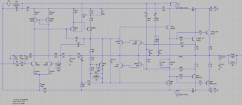
1. Incorporate elements of the blameless amp into the Kenwood power amp. Add a current mirror to equalize current through the LTP, add emitter degeneration to the LTP, increase current through the LTP to 2mA per device which is 3x the factory design, switch to EF2 output stage with a "speedup" cap. See LTspice schematic, below.
2. Add shielding between the left channel power amp PCB and the supply lines running out of the mains transformer.
3. Remove the "PUSH SW A" PCB from the signal chain. This disables the high and low filter function and the tone controls. It removes a single-transistor gain stage whose distortion floor (by itself!) is pretty loud, 65db below signal for a large yet plausible signal, as reported by spice.
4. Replace the TA7136 opamp on the TONE PCB with a modern opamp. With "PUSH SW A" gone this is the only gain stage in the preamp. I used one OPA627 per channel. (In hindsight there are probably better choices.) Adapter boards exist that let you replace the TA7136 with any single or dual opamp, I used a "Brown Dog" adapter which fits OK in the Kenwood. The new opamps are biased into class A by .91mA current sources drawing current from their outputs.
This is covered in more detail on a pair of threads at Audiokarma. Sorry about the cross post, hope that's allowed. Cheers!
This post is about a completed project. The goal was to improve a vintage Kenwood KR-9400 receiver (120wpc, 0.1% THD spec'd power amp, maybe even worse preamp) to near-blameless levels of distortion, like 0.01% THD+IMD+noise from "AUX" input to speaker outputs.
I made these changes, none needing PCB mods:
1. Incorporate elements of the blameless amp into the Kenwood power amp. Add a current mirror to equalize current through the LTP, add emitter degeneration to the LTP, increase current through the LTP to 2mA per device which is 3x the factory design, switch to EF2 output stage with a "speedup" cap. See LTspice schematic, below.
2. Add shielding between the left channel power amp PCB and the supply lines running out of the mains transformer.
3. Remove the "PUSH SW A" PCB from the signal chain. This disables the high and low filter function and the tone controls. It removes a single-transistor gain stage whose distortion floor (by itself!) is pretty loud, 65db below signal for a large yet plausible signal, as reported by spice.
4. Replace the TA7136 opamp on the TONE PCB with a modern opamp. With "PUSH SW A" gone this is the only gain stage in the preamp. I used one OPA627 per channel. (In hindsight there are probably better choices.) Adapter boards exist that let you replace the TA7136 with any single or dual opamp, I used a "Brown Dog" adapter which fits OK in the Kenwood. The new opamps are biased into class A by .91mA current sources drawing current from their outputs.
This is covered in more detail on a pair of threads at Audiokarma. Sorry about the cross post, hope that's allowed. Cheers!
Attachments
Last edited:
Hi, I usually remove the speaker selector switch and make a better path from the output to the binding posts.
So, how does it measure after you've made the changes?
The power amp section looks good in LTspice, THD+IMD floor is >80db below signal even in the upper octaves. How would you measure the real amp? Loopback into a PC sound interface?
you will want about a 100:1 voltage divider with diode protection for the sound card input. you will also want a sound card with 192khz sampling frequency id you plan on doing distortion measurements at 20khz (and expect them to be anywhere near accurate).
Why? Then you won't be able to choose between headphones and speakers.Hi, I usually remove the speaker selector switch and make a better path from the output to the binding posts.
The Kenwood has a fun compensation topology. It has the usual miller cap at Ce9, and it has another cap at Ce8 that creates a "feed forward" path. This is a 2nd feedback loop that bypasses the output stage at HF. This allows a smaller Ce8, and it allows more gain through the front-end, but not much more: with too much gain you can oscillate through the feed-forward path!
OK, so what's the best combination of Ce8 and Ce9?
I got serious about SPICE modeling, created some models from the datasheets:
# .model 2sb536 pnp( CJC=7.7e-11 TF=4e-09 TR=2.38e-07 CJE=2.45e-10 RC=0.333333333333333 VAF=100 IKF=1.05 IS=3e-15 )
# .model 2sb539 pnp( CJC=9.24e-10 TF=2.28571428571429e-08 TR=1.19e-06 CJE=2.94e-09 RC=0.05 VAF=100 IKF=7 IS=2e-14 )
# .model 2sd287 npn( CJC=6.6e-10 TF=2e-08 TR=1.19e-06 CJE=2.1e-09 RC=0.05 VAF=100 IKF=7 IS=2e-14 )
# .model 2sd381 npn( CJC=5.5e-11 TF=3.55555555555556e-09 TR=2.38e-07 CJE=1.75e-10 RC=0.333333333333333 VAF=100 IKF=1.05 IS=3e-15 )
First surprise: the amp schematic in the OP, the one I had built and played for several hours during a party with guests over, isn't stable in Spice with these transistor models! It was stable in real life. That's good news -- we want the spice models to be conservative. We'd like to think that anything stable in Spice would be stable in real life. That's been the case so far, for this particular set of transistors and circuit topology.
The existence of Ce8 is a departure from the pure blameless amp that has no feed-forward path. So I tried the real amp with only a 56p at Ce9, and open circuit at Ce8. This runs stable, and it sounds bright and thrashy! That was the second surprise. The corresponding simulation looks pretty good, distortion floor is 87db down from signal (1k+14k IMD test.) It's weird to think that an amp that measures pretty good can sound harsh. It wasn't that super harsh, and it did a lot well, sounded airy and transparent sometimes, and sometimes it wasn't really fun to listen to.
After running a LOT of experiments with different component values I zeroed in on the new attached schematic. Ce8 is 1p, Ce9 is 22p, and the degeneration resistors on the LTP increase to 220ohm. It's stable in SPICE to at least a factor of two; you can reduce or increase either Ce8 or Ce9 by at least a factor of two and nothing oscillates. It also gives a distortion floor 95db below signal in Spice for the 1k+14k IMD test. This is built, it's playing now, and it sounds fine. It sounds neutral, not harsh, but just right. At least so far. 🙂
Third surprise: the Kenwood is sensitive to bias current in the output stage. At 30mA it hurts my ears, sounds real congested. At 50mA it sounds sweet. My guess is that the feed-forward path interferes with the regular feedback path's ability to correct crossover distortion, esp. at HF. That's a problem if you have low bias current and bad crossover distortion to begin with, less of a problem with ideal bias current and a smoother and wider crossover region. It could also be my imagination, psych effects at work. 🙄
Attachments
Is it normal for bias current to vary with temperature by a factor of 2?
If you set the KR-9400 so its bias current is 50mA when cold, it can reach 95mA after a warm-up. That seems like a lot of variation...
Everyone knows bias current is critical and SPICE agrees. In SPICE if you play a 3kHz tone through this amp, the 5th harmonic is 100db below signal with 33mA of bias current, and 120db below signal with 76mA of bias current.
So the next phase of this project is to improve the temp compensation.
The factory circuit uses a thermistor on the heatsink, a "5TP-41L". I don't suppose anyone has a datasheet on something like this...
These are the tests I was running in LTspice, all driving a 4-ohm load through the Zobel network unless otherwise specified:
1. Intermodulation distortion (IMD) test. Input is the sum of 130mV @ 1kHz sinewave and 100mV @ 14kHz sinewave. Result is the S/N ratio from the 14kHz signal down to the nearby IMD distortion products.
2. Transient intermodulation distortion (TIM) test. Input is the sum of a 0.2V sinewave @ 5kHz and a squarewave alternating between 0.2V and -0.2V at 50kHz using 0.1usec rise and fall times. Result is the S/N ration from the 5kHz signal down to its audible (<20kHz) distortion products.
I know there's controversy about TIM. I do not claim that TIM matters but I'm sure it exists, SPICE shows differences very easily here.
3. Output impedance test. Input signal is 130mV sinewave @ 1kHz. Output is connected to a 19kHz 1A sine current source instead of the 4-ohm load. Result is the S/N ratio (1kHz is the signal, 19kHz is the noise.)
4. Crossover distortion test. Same as prior test for output impedance, except the bias current is adjusted down to a fraction of 1mA.
5. Higher order harmonics test. Input is a 1V sinewave @ 3kHz. Result is the amplitude of the 5th, 7th, 9th, and 11th harmonics. (This is on the psychoacoustic theory that harmonics don't sound bad until the 5th harmonic. Every odd harmonic from the 5th on sounds toxic super bad!)
Those may not be the best tests that could possibly exist -- please criticize them! They were better than nothing, that is all I claim.
After taking a LOT more spice measurements for different compensation cap values and LTP emitter-degeneration resistor values I came up with the attached LTspice schematic, which is built and playing and sounds great!! And it has similar character to the original factory design, it's warm and mellow.
This is what changed:
- LTP emitter resistors are back to 100ohm. Ce9 is 12pF. This combination gives nearly the same gain through the LTP and VAS as the factory design.
- Ce8 is 2pF. These Ce9 and Ce8 values give better stability than the factory 10pF/1pF combination. The factory compensation was so marginal that a service bulletin changed it to 10pF/3pF! The service bulletin values aren't the best in simulation though, 12pF and 2pF bests them across most tests without giving up stability margin. You can cut either the 12pF or the 2pF capacitor in half and it still simulates stable, barely.
- I added a 1uF cap across the bases of the driver transistors. This improved linearity a little, with no apparent drawback. There's plenty of space for it.
Attachments

Found and fixed 3 more bugs in the original design since last post...
1- There are a pair of coupling caps at the input to the TONE AMP PCB, they're polar tantalum caps, 0.47uF and 35V. The problem is, they're mildly reverse biased and have been for 40 years. That can't be good. The fix is to replace them with a jumper. That cleaned up the sound a LOT, another veil was lifted.
2- There's an opamp on the PUSH SW B PCB which drives EQ circuits for phono/AM/FM/mic inputs. It shouldn't be in the signal path for AUX in, but it is! Its output is mixed with AUX in at the inputs to the next stage. This opamp is basically quiet when the input selector is at AUX, but I don't trust it to be 100% quiet and completely reject supply noise etc. The fix is to use tape inputs, not AUX.
3- There are power supply filter caps on the TONE AMP PCB, rated for 47uF 10V, and they are exposed to 14V all the time and have been for 40 years. That's not good. So those are replaced with higher rated caps.
"Shielding? We've heard of it"
When the -9400 left the factory, the half-wave currents in the supply rails shared the power supply PCB with the amp inputs, the output rails, and the output inductors. The output inductors in particular were ideally positioned to pick up both half-wave signals and also ripple current flowing from the rectifier into the filter caps. There was very little shielding between supply rails and the feedback network section of the amp PCB.
The general risk is that half-wave-distorted currents can create magnetic fields that induce half-wave-distorted voltages in nearby signal wires. Cordell's book says you want to keep larger distorted currents away from the amp inputs, the feedback network, and the output inductors. Makes sense.
In the case of the Kenwood, each output rail is sandwiched between the power rails for several inches, outside the NFB loop. I did a back-of-the-envelope calculation: mutual inductance could be up to 100s of nH, that could give you on the order of .1% distortion at 20kHz just by direct interaction between the supply rails and the output rail. That could be audible by itself.
Adding Separation
There's lots of open space in the -9400. I moved the output inductors to free space off the power supply PCB, below one of the tuner PCBs. This doesn't make the output rails any longer, it was already on the output rails' path to the speaker selector switch at the front panel.
I rerouted the power rails up over the top of the unit, direct to the power transistors, twisting together the pos and neg rails to minimize half-wave emissions. (The sum of the pos and neg rails is an undistorted current.)
I added shielding around the input and NFB parts of each amp PCB. A square cut from an aluminum can and wrapped in packing tape works well, so long as it's grounded to the frame.
Rerouting the power rails led to audible oscillation -- a kind of ghostly singing at about 10kHz. Not loud, fortunately. The scope showed a bunch of high frequency junk with a weird 10kHz beat over it. The new rails are longer and using twisted pair probably adds more inductance than the original rails on the PCB. The singing was worse on the left channel which has longer rails. Spice shows this oscillation if you model each supply rail to the output transistors as a 1uH inductor. Spice also suggested that a small (100nF to 1uF cap) in series with a small (1 to 10 ohm) resistor would damp out the oscillation if placed between frame ground and the output transistor collectors. That worked in real life too using 1uF caps and 10R resistors.
Pics to follow.
So, apparently it's critical to minimize input and output capacitance for the input pair, current mirror, and VAS input stage? I made some bad choices back in October. One channel has 2n1893's for the current mirror (55pF Cebo, 15pF Ccbo). Don't even ask. The channels sound a little different and I suspect this is why. The other channel has 2n2222's which are a less terrible choice for a current mirror, still not the best.
Live and learn. The new plan is to swap in KSA992 / KSC1845's for the input stage, the same ones the honey badger amp uses. They have ~2pF Ccbo.
In Spice those simulate very nicely. The distortion floor lies more than 100db below the signal for a 19kHz + 20kHz IMD test. You can get away with even less compensation. For example, Spice is stable with Ce8 = 2pF and Ce9 open. For the real circuit, I will probably leave Ce8 at 2pF (it has a C0G ceramic in there now) and swap out the non-C0G 12pF cap in Ce9 for a C0G 6pF or 10pF cap.
Found and fixed 3 more bugs in the original design since last post...
1- There are a pair of coupling caps at the input to the TONE AMP PCB, they're polar tantalum caps, 0.47uF and 35V. The problem is, they're mildly reverse biased and have been for 40 years. That can't be good. The fix is to replace them with a jumper. That cleaned up the sound a LOT, another veil was lifted.
Tants can take as much as 30% of their rated voltage in reverse (so about 10V). I don't think they ever saw anything near that in a line level stage.
Getting to 0.005% distortion into 4 ohms
This revised schematic goes where no plebian, Miller-swilling Kenwood has gone before!
It has these nice properties:
* 60 degrees phase margin, 35db gain margin.
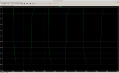
* Square wave looks clean. It rings a tiny bit, damps out quickly. The attached screenshot is a 50kHz square wave.
* On a 19kHz + 20kHz IMD test, the 18 and 21kHz distortion products are about 87db below signal, worst case. (Worst case means the output stays in the crossover region most of the time, while driving a 4 ohm load.)
The changes are:
* Cmod3 is new. It improves phase margin.
* KSA992 in the long-tailed pair, KSC1845 in the current mirror. (The BC327's previously in the long-tailed pair were overvolted. Oops.)
* KSC3503 at Q4 is faster than the Ford-administration-era 2SD381 that shipped from the factory. This improves phase margin.
* Miller cap Ce9 is reduced to 6pF. This consumes some phase margin, in return we get better open-loop gain and more feedback at HF.
The changes aren't built into the real amp yet. I'm waiting on the 2SC3503's. With luck it'll be stable...
Also new are the 1uH inductors on the power rails near the output transistors. These represent some parasitic inductance in the rails. The neighboring 1uF cap and 10R resistor prevent oscillation due to the rail inductance. This change is built in the real amp and works well.
This revised schematic goes where no plebian, Miller-swilling Kenwood has gone before!
It has these nice properties:
* 60 degrees phase margin, 35db gain margin.
* Square wave looks clean. It rings a tiny bit, damps out quickly. The attached screenshot is a 50kHz square wave.
* On a 19kHz + 20kHz IMD test, the 18 and 21kHz distortion products are about 87db below signal, worst case. (Worst case means the output stays in the crossover region most of the time, while driving a 4 ohm load.)
The changes are:
* Cmod3 is new. It improves phase margin.
* KSA992 in the long-tailed pair, KSC1845 in the current mirror. (The BC327's previously in the long-tailed pair were overvolted. Oops.)
* KSC3503 at Q4 is faster than the Ford-administration-era 2SD381 that shipped from the factory. This improves phase margin.
* Miller cap Ce9 is reduced to 6pF. This consumes some phase margin, in return we get better open-loop gain and more feedback at HF.
The changes aren't built into the real amp yet. I'm waiting on the 2SC3503's. With luck it'll be stable...
Also new are the 1uH inductors on the power rails near the output transistors. These represent some parasitic inductance in the rails. The neighboring 1uF cap and 10R resistor prevent oscillation due to the rail inductance. This change is built in the real amp and works well.
Attachments
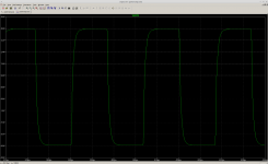
Using 8p at Cmod3 makes an even prettier square wave. Also the AC analysis frequency response does not peak before rolling off, it just rolls off smoothly. I guess this is more stable the with the 12p at Cmod3.
Using 8p produces somewhat worse phase margin than 12p, but I don't think I believe that? I have also been computing phase margin and gain margin by breaking the negative feedback loop with a 1GH inductor at the base of Q2, running AC analysis, and comparing the response of the input to Q1 with the response at the feedback node. This alters the circuit a bit, so you can't trust it for exact numbers. I guess you have to close the feedback loop for final tuning and do without super precise phase margin / gain margin numbers.
Latest LTspice schematic is attached.
Attachments
You will find in the real world, that to approach "Blameless" performance you need to follow Self's script a little closer and find the working, not simplified schematic. Here's the real model's AP measurement from the sales website: The Signal Transfer Company: Compact Blameless Power Amplifier .
If other projects are anything to go by, Spice modelling will show typically about 10 times better THD figures than real amplifiers. As the real model amplifier measures <0.0004% midband, imagine what the simulations might have predicted. 😉
There are a few features needed here, like a current source for the LTP and the VAS, RC filtering to the front end, diode clamps and flying catch diodes that should be on the schematic by this stage. I don't know how you see a bootstrapped capacitor loaded VAS as "blameless" but you can be very certain that you won't find that in one of D. Self's creations. No doubt you'll realize this design needs more help than what simulation predicts will qualify it as "blameless" which, after all, is a performance level, not a design topology, for any who are in doubt.
Last edited:
Self has a VAS with the same topology here, it can't be that bad.
Adding a current source for the VAS yields a 1db lower distortion floor. Nice. Maybe because Q4 is less loaded.
What projects have 10x worse distortion than Spice predicts? That can't be universally true. If you minimize the issues that can't be represented on the schematic -- inductance from the output rails into the feedback network, nonlinear ceramic caps, etc. -- Spice should be accurate.
I think you missed the point of that article you linked which is Self's thesis for ridding amplifiers of all sub-optimal topologies like the capacitor bootstrapped VAS shown. He certainly hasn't endorsed it or offered it as an acceptable alternative. I meant what I said in that you won't find that in any of his designs, so associating it with blameless qualities just makes no sense.
In the VAS distortion section (5.2) the basic CS variation is shown in fig. A and with enhancements in figs C,E,F . The accepted bootstrapped version is F which doesn't use an electrolytic capacitor but requires the addition of a buffer amplifier for the output of the stage as well as a bootstrapping resistor - quite a different beast to the normal version B, as in the Kenwood and countless other, older amplifiers.
Having said this, there's no reason you can't do whatever you like to improve your amplifier but my suggestion is to not go overboard in trying to clean up a basically good sounding amp. Many people fell into the trap of thinking low THD was a panacea for all SQ problems back 20 years ago when Self's work was becoming widely known.
It seems though, that a lot of audiophiles were accustomed to high levels of nice, low order harmonic distortion and instantly disliked the qualities of blameless amplification.
Not much has changed since then, either.
Well put Ian, each have their own subjective opinions on SQ verses implementation.
As a designer trying to roll your own, it is what makes it so interesting hearing every ones opinions and trying to make sense of it all 🙂
I guess my take is to have a common PS platform/setup and plug-in as many topologies/implementation as you can and give them a test/listen and draw your own conclusions.
It is hard to draw listening conclusions based on a shematic!
Today I am listening using Si4735/MAX9729/TPA3100D2/Dynaudio Gemini's spkrs. Source, a FM radio station 75 miles away and it sounds pretty good to me even when it is raining. On paper, it is a mediocre design, see what I mean?
I posted a Sansui AU-X1 design on this forum for discussion.
Good luck jpc2001 with your kr-9500 mod,
I'll take a closer look at the original design. Looks to be a really nice layout, esp the main amp pcb is what I can figure to be a edge finger connectors?, which makes it a treat to service/mod.
Are you going to mod the existing pcb or make a new one? I suggest to leave the original as is, so it is easy to compare against a new design as simple as plug and play?
Not too sure about incorporating the thermistors into the bias ckt, that is different than what others have done using a Si junction as the thermal FB mechanizm.
This -9400 is comparable in design construction to the popular Pioneer SX-1050
Good luck
Rick
- Status
- Not open for further replies.
- Home
- Amplifiers
- Solid State
- Blameless vintage big-watt receiver