Hi...
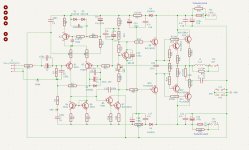
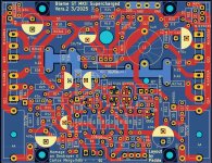
I have made a pcb based on the Blame ST MKII schematic V1, everyone can find i the internet. For the first test i used 100 ohm 3 watt resistors with a voltage of +-35 volts.
I could adjust the same voltage drop over the resistors of about 4,7 volts. No bad smoke, not heat.
Today i tried to adjust the bias to 13 mv with a railvoltage of +-55 volts, delivered from a Connex SMPS. But it isnt possible to adjust the bias right. If i try and the bias reaches 10 mV suddenly the bias rises up to 34 mV.
There is no difference if i trimm the pot or make a adjustment in ohm and power up later...10 mV through warming up and the the bias suddenly jumps up to 34 mV.
If i trimm down it is not possible too to reach the 13 mV. Reaching a certain point the bias voltage jumps down to 4,9 mV.
I have compared my kicad schematic with the original schematic and can not find a mistake in the moment. I had built the BLAME ST and all was fine. It has the same components for bias adjusting on board.
The only difference between the older Blame ST and the now newer MKII is using a starpoint and a connection from the starpoint to the groundlift resistor GNDA. Also using a loop breaker.
But i think that is not the reason of the strange behavior.
Perhaps someone has an idea to search for or a solution for this problem.
Thanks
Peter
Attachments
Forgot to mention...is the same on each channel.
I took one heatsink with the board out now and measured all resistors. All resistors have the right value...
I took one heatsink with the board out now and measured all resistors. All resistors have the right value...
I suspect the 10R hum buck resistor is the issue. As an experiment, try installing a short across this resistor and see if the behavior changes.The only difference between the older Blame ST and the now newer MKII is using a starpoint and a connection from the starpoint to the groundlift resistor GNDA. Also using a loop breaker.
But i think that is not the reason of the strange behavior.
Good luck.

Hi BSST,
for the first i disconnect the wire from signalground to the starground. Second try will be shorting the groundlift resistor.
I will report...
Thank you
for the first i disconnect the wire from signalground to the starground. Second try will be shorting the groundlift resistor.
I will report...
Thank you
Your common connection between the positive and negative supplies should join together, and a common wire from their junction and the return wire from the speaker should join at the node marked "GND".
To elaborate, the supply current dawn from each supply is highly non-linear, but the sum of their two currents in the common return wire is linear. You want that linear supply current to join the linear current returning from the speaker in a direct manner, with low loop area. This helps ensure that no distortion artifacts intrude at the amp's differential inputs (Q1, Q2) along the signal ground and feedback ground path.
How best to join that signal/feedback ground node to the high current node is more subtle, but was being addressed by the star grounding approach you alluded to. A ground break resistor probably joined star common to the chassis. Often the shell of the RCA jack is isolated from the chassis to avoid an internal ground loop. Lots of various approaches and discussion.
Last edited:
Sounds like it could be oscillating. Did you put an oscilloscope on the output?
Hi...
I own a OWON oscilloscope 2x100 MHz, but i cant use it, have to learn...think it is time...
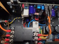
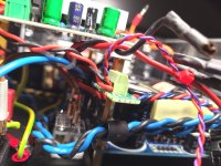
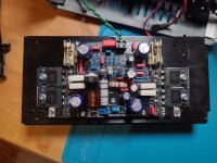
Positive and negative supply wires are at one point of the SMPS output. In front of the output is my starground. The wires GND/+55V/-55V are drilled together and go to the boards as short as possible.
Not easy to get good pictures....
The net wires black/blue have enough space to the other wires or components and and are drilled too.
I have disconnect one wire from starground and signalground now, easy because i use faston connectors, and will see what happens...
Greets
Peter
I own a OWON oscilloscope 2x100 MHz, but i cant use it, have to learn...think it is time...
Positive and negative supply wires are at one point of the SMPS output. In front of the output is my starground. The wires GND/+55V/-55V are drilled together and go to the boards as short as possible.
Not easy to get good pictures....
The net wires black/blue have enough space to the other wires or components and and are drilled too.
I have disconnect one wire from starground and signalground now, easy because i use faston connectors, and will see what happens...
Greets
Peter
Attachments
Mhmmm...
i have tried 10 ohm, groundlift, shorted and disconnected the wire to the starground...makes nothing better.
I think without using an oscilloscope its hopeless....
Thanks for helping
Peter
i have tried 10 ohm, groundlift, shorted and disconnected the wire to the starground...makes nothing better.
I think without using an oscilloscope its hopeless....
Thanks for helping
Peter
What is this resistor? Load resistor?For the first test i used 100 ohm 3 watt resistors with a voltage of +-35 volts.
Jan
The 100 ohm 3 watt i used for first testing, instead of the fuses in the voltage rails. If someting is wrong they will get up in smoke, but did not happen...
If everything is ok, you can put the fuses in...
Carlos, as he built the Blame Amps in the past, told to measure the voltage dropping over the test resistors. There should be about 4,7 Volts in each rail.
This test was ok...
Peter
If everything is ok, you can put the fuses in...
Carlos, as he built the Blame Amps in the past, told to measure the voltage dropping over the test resistors. There should be about 4,7 Volts in each rail.
This test was ok...
Peter
4.7V across 100R means a current draw of 47mA. That seems to indicate that the bias current is in the ball park.
Was there a change in output stage emitter resistors in this amp like from someone deciding to 'improve' it?
If, the bias current may be OK but the measured setting not.
Jan
Was there a change in output stage emitter resistors in this amp like from someone deciding to 'improve' it?
If, the bias current may be OK but the measured setting not.
Jan
I have not changed any value or component, using Carlos schematic in original, as in the pdf. My schematic is based on the pdf.
My measurement is over one of the 0,22 ohm resistors. The emitter pin is longer, not cut and gets one wire. The other wire is connected to the output track, before the zobel network.
But i have tested only one side, on the npn transistors, will try the other side too...thats a good idea...
Greets
Peter
- Home
- Amplifiers
- Solid State
- BLAME ST MKII Supercharged no bias adjusting possible