Hi,
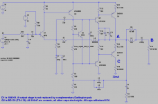
i think, it was Gerhard Haas and Georg Schwarz, who around AD1990 showed a quasi-discrete (Darlington power transistors) amplifier with single supply, single input transistor, single transistor bootstrapped swing and delivering 60W/4R. Edit: It was called Black Devil and published in Elrad. Tiefbassuebertr uploaded the article for this post. Unfortunately, he did not perfectly stabilize high frequencies, hence he could not apply much negative feedback. I am gonna fix this. For another thing, over-load protection was done in the power supply with an extra power transistor and big electrolytic cap. Is that not gonna get cheaper and smaller?
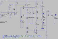
In LTspice IV i have the following theoretical schematic with AC feedback removed by L2. Edit: For protection, add a 1N4148 diode anti-parallel to input diode of input transistor. Also change R3 to 1K and R5 to 820 in order to get more symmetrical swing.

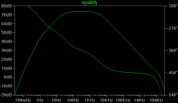
Without deliberate domination, upper limit at A amounts to 10KHz. Now i set dominant lowpass not by Miller effect (which is a lowpass of 1/(2*Pi*Ccb*Rc*voltage_gain)) of swing stage, what would reduce slew-rate and feedback, but with C2 short-cutting output stage. If we use 22pF, upper limit becomes 3500 Hz:

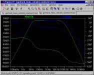
Upper right phase turn (here, 360+90°), where feedback is still well error-correcting, is at a gain of 14dB. For we will have twice that closed-loop-gain, the amp should be very stable in the ultrasonic. For infrasonic we will have only 12dB safety margin -- reduce gain by 12dB, and the thing will oscillate. Let us feed back:

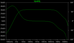
Lowpass is still of first order with tiny 10MHz bump. Highpass is of second order but cannot oscillate, no matter how large feedback and bootstrap Cs are, due to low gain of input stage. We have a whopping 43dB of corrective feedback and must make sure, that feedback loop including power lines encircles only a small area and uses capacitors, which really shortcut HF. Without access to square wave generator and oscilloscope, one could be tempted to double value of C2.
The simulator does not respond to C11, but even using an early Baxandall output stage as shown here, this may be quite good an amp. Hardly any crossover distortion. Clang rises with level, but most loudspeakers produce much higher numbers. 32mA bias shall be in the sweet spot, where HF noise becomes lowest. Now this is oldfashioned and takes time to assemble.
Enter complementary Darlingtons. About push-pull unity-gain buffers: Single-transistor emitter impedance equals 0.025/Ic. Push and pull emitters lay in parallel. So at 31mA bias we have 0R4 source resistance. As this is one tenth of load, crossover clang should be at most -20dB, occuring at around 1V RMS. Simulation thinks different, presenting much lower numbers. But confidentially, simulation is flawed here, we need that bias.
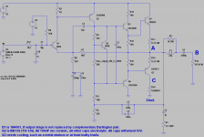
Finally we set in- and output bandwidths to 40KHz. Power supply noise rejection ratio may become enlarged, if source resistance is reduced. R1 is a problem, for it must be able to take a serious load, if peripherals ship-wreck, yet either must not have high inductance or must become shortcut by another Boucherot AKA Zobel cell. Edit: One may raise upper limit frequency to 80KHz, as output stage should be able to handle that.For Darlingtons i picked BD647 and BD648. Q2 needs thermal contact with all power transistors. So we shall have a well-sounding sturdy amplifier like this:

Edit: (For protection, add a 1N4148 diode anti-parallel to input diode of input transistor. Also change R3 to 1K and R5 to 820 in order to have more symmetrical swing.)
Still missing is output shortcut tolerance. I would enact a wire fuse, slow-acting, 3.15A nominal current in each channel in power supply line. Furthermore i would limit peak currents to values depending on collector-emitter voltage, effectively limiting Ptot, in the usual way, which goes to sense voltages over emitter resistors and shortcut inputs of Darlingtons in case of overload. Those 3mm long 0.1W resistors would come in handy in places cramped as these.
It took some time to obtain parts and assemble this Gerhard Haas Rebuild, yes, but here on earth we have few things to spend other than time.
Uli
i think, it was Gerhard Haas and Georg Schwarz, who around AD1990 showed a quasi-discrete (Darlington power transistors) amplifier with single supply, single input transistor, single transistor bootstrapped swing and delivering 60W/4R. Edit: It was called Black Devil and published in Elrad. Tiefbassuebertr uploaded the article for this post. Unfortunately, he did not perfectly stabilize high frequencies, hence he could not apply much negative feedback. I am gonna fix this. For another thing, over-load protection was done in the power supply with an extra power transistor and big electrolytic cap. Is that not gonna get cheaper and smaller?
In LTspice IV i have the following theoretical schematic with AC feedback removed by L2. Edit: For protection, add a 1N4148 diode anti-parallel to input diode of input transistor. Also change R3 to 1K and R5 to 820 in order to get more symmetrical swing.
Without deliberate domination, upper limit at A amounts to 10KHz. Now i set dominant lowpass not by Miller effect (which is a lowpass of 1/(2*Pi*Ccb*Rc*voltage_gain)) of swing stage, what would reduce slew-rate and feedback, but with C2 short-cutting output stage. If we use 22pF, upper limit becomes 3500 Hz:
Upper right phase turn (here, 360+90°), where feedback is still well error-correcting, is at a gain of 14dB. For we will have twice that closed-loop-gain, the amp should be very stable in the ultrasonic. For infrasonic we will have only 12dB safety margin -- reduce gain by 12dB, and the thing will oscillate. Let us feed back:
Lowpass is still of first order with tiny 10MHz bump. Highpass is of second order but cannot oscillate, no matter how large feedback and bootstrap Cs are, due to low gain of input stage. We have a whopping 43dB of corrective feedback and must make sure, that feedback loop including power lines encircles only a small area and uses capacitors, which really shortcut HF. Without access to square wave generator and oscilloscope, one could be tempted to double value of C2.
The simulator does not respond to C11, but even using an early Baxandall output stage as shown here, this may be quite good an amp. Hardly any crossover distortion. Clang rises with level, but most loudspeakers produce much higher numbers. 32mA bias shall be in the sweet spot, where HF noise becomes lowest. Now this is oldfashioned and takes time to assemble.
Enter complementary Darlingtons. About push-pull unity-gain buffers: Single-transistor emitter impedance equals 0.025/Ic. Push and pull emitters lay in parallel. So at 31mA bias we have 0R4 source resistance. As this is one tenth of load, crossover clang should be at most -20dB, occuring at around 1V RMS. Simulation thinks different, presenting much lower numbers. But confidentially, simulation is flawed here, we need that bias.
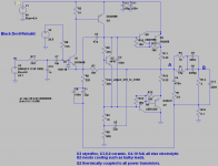
Finally we set in- and output bandwidths to 40KHz. Power supply noise rejection ratio may become enlarged, if source resistance is reduced. R1 is a problem, for it must be able to take a serious load, if peripherals ship-wreck, yet either must not have high inductance or must become shortcut by another Boucherot AKA Zobel cell. Edit: One may raise upper limit frequency to 80KHz, as output stage should be able to handle that.For Darlingtons i picked BD647 and BD648. Q2 needs thermal contact with all power transistors. So we shall have a well-sounding sturdy amplifier like this:
Edit: (For protection, add a 1N4148 diode anti-parallel to input diode of input transistor. Also change R3 to 1K and R5 to 820 in order to have more symmetrical swing.)
Still missing is output shortcut tolerance. I would enact a wire fuse, slow-acting, 3.15A nominal current in each channel in power supply line. Furthermore i would limit peak currents to values depending on collector-emitter voltage, effectively limiting Ptot, in the usual way, which goes to sense voltages over emitter resistors and shortcut inputs of Darlingtons in case of overload. Those 3mm long 0.1W resistors would come in handy in places cramped as these.
It took some time to obtain parts and assemble this Gerhard Haas Rebuild, yes, but here on earth we have few things to spend other than time.
Uli
Attachments
Last edited:
Check out Bob Cordells book and this thread:Hi,
i think, it was Gerhard Haas, who around AD1990 showed a quasi-discrete (Darlington power transistors) amplifier with single supply, single input transistor, single transistor bootstrapped swing and delivering 60W/4R. Edit: It was called Black Devil and published in Elrad. Tiefbassuebertr uploaded the article for this post. Unfortunately, he did not perfectly stabilize high frequencies, hence he could not apply much negative feedback. I am gonna fix this. For another thing, over-load protection was done in the power supply with an extra power transistor and big electrolytic cap. Is that not gonna get cheaper and smaller?
Uli
http://www.diyaudio.com/forums/solid-state/171159-bob-cordells-power-amplifier-book.html
and send to him a PM.
Add in the headline of this thread the terms "ELRAD" and "Black Devil"
Tiefbassuebertrager, i thank thee! Dear Gannaji, here they are:
Thank you !
Thou are welcome! I managed to make it short-cut safe by giving it 4 Ohms output resistance:

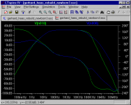
Putting shunt resistor R10 at positive output pin proved too difficult, hence load has no common ground. K2 is at most -60dB, k7 at most -80dB. Response to 4 Ohms (blue is A, green B):

To 100 Ohms gain is 6 dB higher:

Using strong Darlingtons and a fast acting 1.25A wire fuse in power rail this should be safe. All power amplifiers should have an output impedance equalling loest load impedance, and all loudspeakers should be designed for a source impedance equalling their nominal impedance.
Putting shunt resistor R10 at positive output pin proved too difficult, hence load has no common ground. K2 is at most -60dB, k7 at most -80dB. Response to 4 Ohms (blue is A, green B):
To 100 Ohms gain is 6 dB higher:
Using strong Darlingtons and a fast acting 1.25A wire fuse in power rail this should be safe. All power amplifiers should have an output impedance equalling loest load impedance, and all loudspeakers should be designed for a source impedance equalling their nominal impedance.
Attachments
")
I have found with this topology that turn on thump can be pretty horrendous unless you take steps to reduce it. One trick that can improve the situation is to enclose the output cap in the feedback loop. If you do that be sure to swap this cap and the output inductor so the latter is outside the loop.
This will also improve LF distortion, which will be pretty bad with such a small cap. If you are planning to use this amp to drive full range speaker you really should replace it with something much bigger.
Another tip for reducing distortion is to bias the drivers into class A by putting a resistor across the emitters of Q5 and Q6 and removing R12, R13. 220R is a common value giving a standing current of about 6mA. Normally you see a charge suck out cap of about 470n to 1u in parallel with this resistor. Personally I prefer to bias the drivers hot with a resistor of about 47R or 68R and leave out the cap. Normally that would require a fairly substantial heatsink for the drivers, although if the rail voltage is indeed 40V one may not be necessary.
- Status
- This old topic is closed. If you want to reopen this topic, contact a moderator using the "Report Post" button.
- Home
- Amplifiers
- Solid State
- Black Devil Improved