Hi
In the process of trying to fix a major hum problem in a tube line stage, I stumbled on a weird temporary solution. I think this weird fix is trying to tell me what the underlying problem is, but being relatively inexperienced with electronics and tubes I haven’t a clue.
Background and sad story of woe:
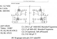
For the output stage of a DAC I choose to use John Broskie’s BCF_9 broskie cathode follower board (to take the balanced output of the DAC and convert it to an unbalanced signal for my audio system).
John Broskie from GlassWare audio design has an excellent reputation for making decent circuits and PCBs but unless there is a missing or broken part he doesn’t respond to emails for technical questions like what follows:
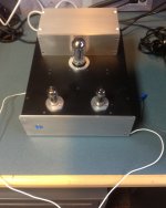
As you can see from the pics the build is nearly complete. I probably should have first tested the BCF_9 board before installing it but I thought I would just go for it.
Couple of days ago I checked the power supply voltages (H+ 12.7 VDC, B+ 300VDC, H- set to 1/4 B+), installed the tubes and was dismayed to have a major hum/buzz from the left channel. Also I would get a repetitive ticking sound.
Right channel is quite. Sound is overall very good from both channels but the hum/buzz/ticking from the left channel too loud to take.
I swapped tubes, tried a different set of 12BH7 tubes, checked all parts to make sure they were the recommended values (see circuit diagram), doubled checked with connections and resistor values with VOM, checked and reflowed every solder connection (twice). Still the left channel hums/buzzes and intermittently ticks (with or without an audio signal input). Completely disassembled and tested still hum in left channel
Pulled the tubes and the noise stops
Tried to trace the hum using an oscilloscope . I think the left channel noise signal is around 60Hz (compared to a signal generator) but not smooth (more saw tooth like and pretty distorted). But this is my first attempt using a scope.
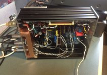
What I did find is that the noise could be readily detected on left channel tube pins (V1 in diagram) 3 and 6.
However when I probed pin 2 or pin 1 the noise stopped. Note: I was using a 1x probe with ground attached to B-/ground. By chance I came upon the fact that the noise also stopped if I touched pin 2 or pin 1 with a test lead/probe that was not connected to anything.
So I tried several lengths of wire soldered directly to tube V1 pin2 (white wire in pics). To completely suppress the hum/buzz and ticking in the left channel the wire on pin 2 must be about 2-3 ft long and needs to be stretched out (cannot be wound into a smaller coil).
This seems antenna_ish to me with the wire influencing some reactive circuit. There must be a bad part or connection somewhere (V1 + input stage?). But how do I determine which component is defective and/or how to really fix it? Beside trying more voodoo?
This is driving me nuts and I would greatly appreciate your advice before I toss this cursed thing out
In the process of trying to fix a major hum problem in a tube line stage, I stumbled on a weird temporary solution. I think this weird fix is trying to tell me what the underlying problem is, but being relatively inexperienced with electronics and tubes I haven’t a clue.
Background and sad story of woe:
For the output stage of a DAC I choose to use John Broskie’s BCF_9 broskie cathode follower board (to take the balanced output of the DAC and convert it to an unbalanced signal for my audio system).
John Broskie from GlassWare audio design has an excellent reputation for making decent circuits and PCBs but unless there is a missing or broken part he doesn’t respond to emails for technical questions like what follows:
As you can see from the pics the build is nearly complete. I probably should have first tested the BCF_9 board before installing it but I thought I would just go for it.
Couple of days ago I checked the power supply voltages (H+ 12.7 VDC, B+ 300VDC, H- set to 1/4 B+), installed the tubes and was dismayed to have a major hum/buzz from the left channel. Also I would get a repetitive ticking sound.
Right channel is quite. Sound is overall very good from both channels but the hum/buzz/ticking from the left channel too loud to take.
I swapped tubes, tried a different set of 12BH7 tubes, checked all parts to make sure they were the recommended values (see circuit diagram), doubled checked with connections and resistor values with VOM, checked and reflowed every solder connection (twice). Still the left channel hums/buzzes and intermittently ticks (with or without an audio signal input). Completely disassembled and tested still hum in left channel
Pulled the tubes and the noise stops
Tried to trace the hum using an oscilloscope . I think the left channel noise signal is around 60Hz (compared to a signal generator) but not smooth (more saw tooth like and pretty distorted). But this is my first attempt using a scope.
What I did find is that the noise could be readily detected on left channel tube pins (V1 in diagram) 3 and 6.
However when I probed pin 2 or pin 1 the noise stopped. Note: I was using a 1x probe with ground attached to B-/ground. By chance I came upon the fact that the noise also stopped if I touched pin 2 or pin 1 with a test lead/probe that was not connected to anything.
So I tried several lengths of wire soldered directly to tube V1 pin2 (white wire in pics). To completely suppress the hum/buzz and ticking in the left channel the wire on pin 2 must be about 2-3 ft long and needs to be stretched out (cannot be wound into a smaller coil).
This seems antenna_ish to me with the wire influencing some reactive circuit. There must be a bad part or connection somewhere (V1 + input stage?). But how do I determine which component is defective and/or how to really fix it? Beside trying more voodoo?
This is driving me nuts and I would greatly appreciate your advice before I toss this cursed thing out
Attachments

In my experience hum usually comes from poor ground wiring.
Its vital that power supply surging on the peak of the supply voltage causing pulses of current in the ground wire don't get into the audio signal chain.
In valves you have the extra dimension of heaters which can cause pick up if not carefully wired and routed.
I built a valve mixer and it hummed very badly.
Changing to DC heaters made a small difference.
However rerouting the ground wire from transformer to power supply capacitors and then to amplifier made a big difference.
I helped work on an amp with a similar problem. Heater AC bleeding into one channel.
Everything was swapped. No change.
Lifted various components. No change.
Ran wires off board to a separate stand alone tube socket. (completely bypassed the original socket with a new output tube and socket) No change.
Finally tracked it down to a problem with the tube socket, but the thing is, the socket and all soldering looked fine, even with an 8 power loop.
No amount of wiggling or poking of the individual socket pins made any difference when checking with a meter.
Eventually out of frustration unsoldered the tube socket and it finally stopped. Close inspection revealed nothing. Solder it back in and all was fine. Must have been an extremely small solder whisker somewhere that was hidden underneath the socket.
You're probably seeing a parasitic oscillation. Cathode followers oscillate just fine without some resistive degeneration at their outputs. I'd try just removing their cathode resistor bypass caps to see if that's enough.
All good fortune,
Chris
All good fortune,
Chris
Hi Sybednar,
C5, according to Broskie's documentation on the BCF-9, connects pin 9 of the tube to ground on his PCB design.
The 12BH7 you are using uses pin 9 for the heater center-tap. So if you put a capacitor in the C5 location, you are tying the center of the heater to ground through a capacitor.
Since you're using the B+/4 heater bias (if I read your post correctly), this might not matter... But I'd remove it anyway - it could only cause mischief. (The B+/4 heater bias should take care of the problem of heater hum coupling to the top-triode cathode - good that you used it!)
Also, was C10 part of the original design? I was looking at Broskie's manual for the BCF-9, and I don't see any capacitor from the grid of the top triode to ground in his documentation. It's unusual to put an AC bypass directly on the grid of the triode.
The cap is in a relatively high impedance part of the circuit, and could be causing the top triode to motorboat (if it's a "pop-pop" noise at low frequency)
I'd pull that cap out too, unless there's a good reason for it to be in there.
It's also possible that the C10 cap is picking up a bit of hum and injecting it onto the top triode grid - your gimmick antenna is probably injecting AC out-of-phase (and thus cancelling the noise). Your test probe touching the grid is providing a different path to ground, also cancelling the noise and stopping the motorboating.
All "educated guesses" - pull C10 and C5 and see if it takes care of your noise.
Best luck 😎
~ Sam
EDIT - I just noticed that your board is a later version than the board in Brodskie's PDF from the TubeCad website... Might be a design change John put in - there is most certainly a space on your board for C10, whereas on the older version (2009) that was where the input wires went. I'd still pull those two caps - for sure C5 is not necessary (if it connects to pin 9 on the new board 😉 ) and C10 is some kind of bypass cap that IMHO is going to cause mischief. Good luck!
Last edited:
Specific question(s)
[1] if you use shorting-plugs on inputs, does problem go away?
The use of a long 18 gauge wire on pin 2 (the grid of the affected stage) indicates exactly what you surmise: induced pickup of EMF 60/Hz noise from the power supply.
Questions
[2] What are R7, R8 and R9 values?
GoatGuy
[1] if you use shorting-plugs on inputs, does problem go away?
The use of a long 18 gauge wire on pin 2 (the grid of the affected stage) indicates exactly what you surmise: induced pickup of EMF 60/Hz noise from the power supply.
Questions
[2] What are R7, R8 and R9 values?
GoatGuy
Sounds like parasitic oscillation, as Chris suggested. Add or improve grid stoppers. For CFs add a cathode stopper.
Add a grid stopper between R1 and pin 2. The existing resistor is not a grid stopper but part of a low pass filter.
Add a grid stopper between R1 and pin 2. The existing resistor is not a grid stopper but part of a low pass filter.
Parasitic oscillations seem highly likely to me too.. I recommend removing C5 on both channels and reporting back.
Parasitic oscillations seem highly likely to me too.. I recommend removing C5 on both channels and reporting back.
Also remove C10.
BTW - what is the part number for the C5/C10 (blue) caps? It looks like an Epcos logo, possibly a film capacitor, but the "M1091..." doesn't cross. Possibly there is a "Bxxxx" part number on the side?
C10 will be at about B+/2 potential - if the voltage rating is not sufficient then that C10 cap on V1 might be breaking down as it charges towards B+/2 and causing that sawtooth-like waveform you're seeing.
EDIT - Epcos has such a fun marking system... From your closeup photo, it looks like the 2nd line marking is " B7 -u1M(?)305(?)W(something) ".
If I'm reading it correctly, you've got a 0.1uF cap installed at C5 and C10 locations. Way too big, at least for C10 - take them both out.
Last edited:
Problem solved! Thanks
Thanks to everyone for their speedy and helpful suggestions. Based upon the phenotype of the noise and your suggestions I removed C5 and C10 (and the meter of additional wire from pin 2). I was elated to not hear anything. Left and Right channels without input are hum free and the motor boating I was hearing is also gone. Weird how happy this made me and the sound with audio input is very nice
The purpose of C5 and C10 according to Broskie’s manual for the new version of the BCF_9 was to generate a low pass filter (<80kHz cutoff) which John recommended if using the BCF-9 as an output stage for a DAC.
Now that I have removed C5 and C10 will the lack of a low pass filter be a problem when I connect it to a DAC? Should I try different values of caps and resistor in the input section that would not create the motor boating and parasitic oscillation?
Again thanks keeping me from going nuts with this hum issue
Cheers
Sebastian
Below are a few additional responses and answers to some of the questions raised:
Values on R7, R8 and R9 are 1 Meg Ohm. I remember reading about using shorting plugs for trouble shooting hum problems but forgot to test this. What does this test reveal?
how right you two were. Thanks
These caps came with the board from Broskie and the manual recommended C5 and C10 values of 100pF-0.01 uf. Yesterday I spent some time trying to determine what their value but the Epcos website and docs weren’t much help. The label on the top of the caps (same for both C5 and C10) is B7-u?1M305WU. For future reference can you tell me what their value is?
Thanks to everyone for their speedy and helpful suggestions. Based upon the phenotype of the noise and your suggestions I removed C5 and C10 (and the meter of additional wire from pin 2). I was elated to not hear anything. Left and Right channels without input are hum free and the motor boating I was hearing is also gone. Weird how happy this made me and the sound with audio input is very nice
The purpose of C5 and C10 according to Broskie’s manual for the new version of the BCF_9 was to generate a low pass filter (<80kHz cutoff) which John recommended if using the BCF-9 as an output stage for a DAC.
Now that I have removed C5 and C10 will the lack of a low pass filter be a problem when I connect it to a DAC? Should I try different values of caps and resistor in the input section that would not create the motor boating and parasitic oscillation?
Again thanks keeping me from going nuts with this hum issue
Cheers
Sebastian
Below are a few additional responses and answers to some of the questions raised:
Specific question(s)
[1] if you use shorting-plugs on inputs, does problem go away?
Questions
[2] What are R7, R8 and R9 values?
GoatGuy
Values on R7, R8 and R9 are 1 Meg Ohm. I remember reading about using shorting plugs for trouble shooting hum problems but forgot to test this. What does this test reveal?
Parasitic oscillations seem highly likely to me too.. I recommend removing C5 on both channels and reporting back.
Also remove C10.
how right you two were. Thanks
EDIT - Epcos has such a fun marking system... From your closeup photo, it looks like the 2nd line marking is " B7 -u1M(?)305(?)W(something) ".
If I'm reading it correctly, you've got a 0.1uF cap installed at C5 and C10 locations. Way too big, at least for C10 - take them both out.
These caps came with the board from Broskie and the manual recommended C5 and C10 values of 100pF-0.01 uf. Yesterday I spent some time trying to determine what their value but the Epcos website and docs weren’t much help. The label on the top of the caps (same for both C5 and C10) is B7-u?1M305WU. For future reference can you tell me what their value is?
Hi Sy - glad it's working!! Dang, my plan B was to see if I could come up with a way to pick it out of your trash 😀
I could see that your termination resistors were 1Meg from the photo. It was an early question I had as well. Thanks for verifying it, tho'!
Shorting the input is one way to try to isolate the noise source. When the input is open-circuit, the associated wires and components see a high impedance - which can pick up noise. If you ground the input and the noise/hum goes away, then it kind of eliminates noise on the B+ or other internal circuitry.
Just one way to try to narrow down where you are looking - noise sources can be hard to track down, especially after you've used up everything in your "bag of tricks" and have to start isolating sections of the amp to go chasing into.
Very good. This is an Epcos part - they are devilish hard to decipher, Epcos puts a different part number on their components and it's not in their catalog.
I've been through this in the past with their SAW filters. Datasheet has one part number, but they use a different part number to mark the part...
Anyway, they do provide a "decoder sheet" that tells me you have a 0.1uF cap - much too big for that circuit. The voltage rating would be 305V, which is fine, but the capacitor would have cut off much of your high frequency sound even if you hadn't had the noise problems. (EDIT - 47k into 0.1uF gives a lowpass filter with a knee at ~34Hz - a good music filter, but not if you want to listen to music!)
The DAC outputs may need a bit of filtering, to clean up higher-frequency clock noise or aliasing (EDIT - coming from the DAC itself), which is probably why Mr. Broskie added the caps into his design. The high frequency components could cause intermodulation products which will show up in your audio spectrum even though the higher frequency signals at the output from the DAC itself are well above the audio range.
Anyway, you might want to either contact Mr. Broskie for a replacement or just order them from Digikey or Mouser. Be sure to get parts that are rated above ~250V for the input (C10) capacitor - it is biased up to around B+/2, and C10 connects from the grid to ground. C5 can be the same part - it doesn't need the higher voltage rating, but that won't hurt it either.
I'd be inclined to as small a cap as possible - you might not need the C10 cap at all. Play the amplifier for a while, your ears will tell you if there's something wrong.
If you decide to put the C10 caps back in, I'd go with as small as possible on C10. Using 100pF will give you a lowpass filter with a knee at about 34kHz (neglecting Miller capacitance). Using a higher value capacitor will move the filter-knee down, and of course will start to lowpass filter your audio signal more.
Enjoy the fruits of your (hair-tearing) labor! 😎
~ Sam
Values on R7, R8 and R9 are 1 Meg Ohm. I remember reading about using shorting plugs for trouble shooting hum problems but forgot to test this. What does this test reveal?
I could see that your termination resistors were 1Meg from the photo. It was an early question I had as well. Thanks for verifying it, tho'!
Shorting the input is one way to try to isolate the noise source. When the input is open-circuit, the associated wires and components see a high impedance - which can pick up noise. If you ground the input and the noise/hum goes away, then it kind of eliminates noise on the B+ or other internal circuitry.
Just one way to try to narrow down where you are looking - noise sources can be hard to track down, especially after you've used up everything in your "bag of tricks" and have to start isolating sections of the amp to go chasing into.
These caps came with the board from Broskie and the manual recommended C5 and C10 values of 100pF-0.01 uf. Yesterday I spent some time trying to determine what their value but the Epcos website and docs weren’t much help. The label on the top of the caps (same for both C5 and C10) is B7-u?1M305WU. For future reference can you tell me what their value is?
Very good. This is an Epcos part - they are devilish hard to decipher, Epcos puts a different part number on their components and it's not in their catalog.
I've been through this in the past with their SAW filters. Datasheet has one part number, but they use a different part number to mark the part...
Anyway, they do provide a "decoder sheet" that tells me you have a 0.1uF cap - much too big for that circuit. The voltage rating would be 305V, which is fine, but the capacitor would have cut off much of your high frequency sound even if you hadn't had the noise problems. (EDIT - 47k into 0.1uF gives a lowpass filter with a knee at ~34Hz - a good music filter, but not if you want to listen to music!)
The DAC outputs may need a bit of filtering, to clean up higher-frequency clock noise or aliasing (EDIT - coming from the DAC itself), which is probably why Mr. Broskie added the caps into his design. The high frequency components could cause intermodulation products which will show up in your audio spectrum even though the higher frequency signals at the output from the DAC itself are well above the audio range.
Anyway, you might want to either contact Mr. Broskie for a replacement or just order them from Digikey or Mouser. Be sure to get parts that are rated above ~250V for the input (C10) capacitor - it is biased up to around B+/2, and C10 connects from the grid to ground. C5 can be the same part - it doesn't need the higher voltage rating, but that won't hurt it either.
I'd be inclined to as small a cap as possible - you might not need the C10 cap at all. Play the amplifier for a while, your ears will tell you if there's something wrong.
If you decide to put the C10 caps back in, I'd go with as small as possible on C10. Using 100pF will give you a lowpass filter with a knee at about 34kHz (neglecting Miller capacitance). Using a higher value capacitor will move the filter-knee down, and of course will start to lowpass filter your audio signal more.
Enjoy the fruits of your (hair-tearing) labor! 😎
~ Sam
Last edited:
BTW - here is the Epcos marking system PDF. Your cap is on sheet 2, MKT style, 10...27.5mm lead spacing. The first line (starting with "M") is the lot number, and can be disregarded.
The second line has " -u1" (Greek letter "mu"), which is 0.1uF (or 100nF, per sheet 5), "M" is the tolerance (20%) "305" is the voltage rating (don't ask me why 305 instead of 300... a mystery of cap ratings...) and "WU" is the date code (2008, the "U" doesn't seem to follow their decoder sheet but either represents a month or is some internal Epcos code)
Enjoy! 😎
~ Sam
Attachments
Hi Sam
Thanks for all your help fixing the hum/motor boating noise and the "Rosetta stone" for decoding the Epcos cap value labeling.
I installed the C5 and C10 caps (provided by John Broskie) based upon his rationale and recommendation of using a low-pass filter to remove the high frequency DAC noise but as they were unlabeled I had no idea they were 0.1uf. I will certainly try your recommendation of using 100pf caps. Should I add back caps at both the C5 and C10 positions? Also in the case of the BCF circuit how do I calculate the low pass filter -3db corner frequency? I guess what I am asking is which of the resistors and caps in the circuit form the low pass filter? For example, is the filter on the + input determined by the value of the total capacitance (i.e 1/C9 + 1/ C10) and resistance (R1 + R9) or R1 and C10 ? Wish I could recall what I learned in basic physics better. But I am loving the whole process of learning in doing these diy audio projects
Sebastian
BTW - here is the Epcos marking system PDF. Your cap is on sheet 2, MKT style, 10...27.5mm lead spacing. The first line (starting with "M") is the lot number, and can be disregarded.
The second line has " -u1" (Greek letter "mu"), which is 0.1uF (or 100nF, per sheet 5), "M" is the tolerance (20%) "305" is the voltage rating (don't ask me why 305 instead of 300... a mystery of cap ratings...) and "WU" is the date code (2008, the "U" doesn't seem to follow their decoder sheet but either represents a month or is some internal Epcos code)
Enjoy! 😎
~ Sam
The lowpass filter circuit in the BCF on the + input is formed by the output impedance of the DAC driver + R1 working into C10, and on the "-" side by R5 and C5.
If you neglect the DAC driver output impedance, the "+" input lowpass filter knee is located at the frequency where the impedance of C10 equals the resistance of R1. Capacitor impedance is calculated using Xc = 1/(2*Pi*f*C) where "f" is frequency in Hz and "C" is capacitance in Farads.
The kicker is that the "+" filter rolloff can be affected by output impedance of the DAC driver. If the driver output impedance is very low (<< 47k) then you can neglect it. If it is higher, it will tend to lower the lowpass knee frequency.
The "-" side filter has a capacitor (C5) across the feedback resistor R5. I'm not familiar with the BCF topology, but it looks similar to how one would implement an active-filter using op-amps. Putting the capacitor across the feedback resistor lowers the gain as frequency increases, although with this technique the gain response flattens out as the impedance of the capacitor approaches zero...
I think Mr. Broskie gave a range of capacitor values because it really depends on which DAC you use to drive the amplifier.
If the DAC output is well-filtered (to remove the DAC audio artifacts and noise present in all Digital-to-Analog converted signals), then you proably don't need any filtering at all.
If the DAC output is not well filtered, it may have residual noise artifacts that are the result of the digital conversion process. The lowpass filter in the BCF is an attempt to clean-up those artifacts.
Note that a simple RC lowpass filter is not going to give a lot of cleanup. The filter might improve a "slightly noisy" situation, but if the DAC output contains a lot of digital noise then IMHO this simple filter won't do much.
I suspect there was feedback from users of the first version of the BCF boards about DAC noise , and the filters were added as a result.
Whether you actually need any filters or not is something you can test by just listening to music in your system. Your present amplifier state is no filter - so you're hearing the full DAC output spectrum, whatever it is.
Note that this filter will do nothing for power-line hum. That is a totally separate issue. The only thing this filter will do is clean up the high-frequency noise from the DAC that might cause problems.
Without expensive test equipment to look at the output spectrum from your DAC or amplifier, you will probably have to just cut-and-try to see if the filtering makes any difference. Start with the lower value recommended by Mr. Broskie and try different values until you are satisfied with the sound. Note that as you get into the higher capacitor values, you will start to roll-off the high frequency portion of your desired audio spectrum!
As in life, nothing in engineering is free. You never get something for nuthin' 🙂
I hope this helps, and I hope you can enjoy the amplifier without adding more parts and effort. And you're right, it's a good learning experience - the sweet reward of using something that you had to hammer-on for a bit to get it working!
Regards 😎
~ Sam
- Status
- Not open for further replies.
- Home
- Amplifiers
- Tubes / Valves
- Bizzaro fix for hum problem needs explanation! Pretty Please