I threw this circuit together and it is 100% functional as advertised.
My proto on bench is using lab supplies for dc filament, variable bias and variable B+. I've tested B+ 50-275v.
Don't have a 6BA6 at the moment so used a sharp cutoff EF86.
It works fine too. Only difference is control range is more narrow.
Problem is can't get distortion below 2%. Interesting it remains fairly constant across the compression range.
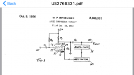
Circuit from expired Collins patent 1956.
https://www.google.com/patents/US27...ved=0ahUKEwiD5Nyy7bjVAhWB5oMKHaGhCbQQ6AEIIzAA
My proto on bench is using lab supplies for dc filament, variable bias and variable B+. I've tested B+ 50-275v.
Don't have a 6BA6 at the moment so used a sharp cutoff EF86.
It works fine too. Only difference is control range is more narrow.
Problem is can't get distortion below 2%. Interesting it remains fairly constant across the compression range.
Circuit from expired Collins patent 1956.
https://www.google.com/patents/US27...ved=0ahUKEwiD5Nyy7bjVAhWB5oMKHaGhCbQQ6AEIIzAA
Attachments
Problem is can't get distortion below 2%. Interesting it remains fairly constant
across the compression range.
Does the distortion reduce if you instead ground G1 and G3, removing the compression?
Does the distortion reduce if you instead ground G1 and G3, removing the compression?
Yes, its now 0.5%. Don't understand that, if i make G1-G3 bias zero then should be same as grounding G1+ G3. I do have a 2.2k ohm fuse in series with bias supply.
Gain is now slightly above 1.0
-
Yes, its now 0.5%. Don't understand that, if i make G1-G3 bias zero then should be same as grounding G1+ G3.
Sounds like the compression is doing the distorting.
Sounds like the compression is doing the distorting.
Problem solved: I made the G1-G3 bias input lo-z, now very low distortion across the entire compression range.
Thanks
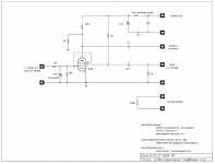
Here is test schematic, as built.
Interesting, do you have any test waveforms?
Yeah but the real meat and potatoes is the side chain circuit. (Just egging you on.)
Yes , been planning side chain for several years. Think I have analyzed every compressor ever built.
Think the solution probably a three way path. Partly existing optical/shunt etc , part newer design and I supect a third so called 'fuzzy logic' ie AI.
AI is much easier and simpler to implement than most imagine.
The pentode still has practical use due to the multiplier function of each grid. Combined with linear and non-linear circuit components it can rival a quad core RISC signal processor.
Raytheon could not replace its 'Hawk' missle guidance system until the mid 70's for same reason. I suspect the pentodes are still in use somewhere.
So the side chain is 'work in progress' but a reliable core was needed first.
Raytheon could not replace its 'Hawk' missle guidance system until the mid 70's for same reason.
I did a brief stint at designing emi protection for rockets (The ones that go fffft then boom, increase the loudness of the fffft and boom by a couple of magnitudes.) More than likely the cost to re-certify the system kept it as is. I suggested a switch on the helicopter to be rated to pass one watt rather than 1/4 watt that the current igniters used. I was told it was not possible.
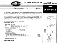
I have several hundred 5702 subminature pentodes just for this compressor project. They work just peachy at -+24vdc. In fact every small signal tube I've tested works great with ~50V potential. The bias is fixed on all of those tests. I start out with full spec sheet voltage and work down. Does the 5672 have any internal connections?
The control/sidechain circuit is a separate project I'm working on. Yes a simple rectifier would work but with limited performance.
As printer2 mentioned, the sidechain is tricky.
-
The control/sidechain circuit is a separate project I'm working on. Yes a simple rectifier would work but with limited performance.
As printer2 mentioned, the sidechain is tricky.
-
Attachments
The main problem that I have with the 5672 is the direct heated cathode. Kind of difficult to work with the bias.
What I've seen in the HiFi world is building a current source to drive the heater and then use that current (through the cathode resistor) to set the bias point.
> to set the bias point.
This is gone way off-topic.
In a compressor VCA, the "bias point" is set by the sidechain, as demanded by the amount of gain reduction needed at the moment. Direct-heat is a minor detail. Generally the type of tube curve is critical, and it is futile to wish to use this or that tube.
jfetter -- the Birkemeier patent claims the Plate Current is "constant" as the control voltage varies (for some unspecified P and G2 resistances). Is that the case?
It matters, because conventional AVC/VCA worked single-ended "thump". Gain is varied by causing a large change of plate current. In audio limiters, the attack time is equivalent to a low bass thump. Some compromise must be made. The high-end is push-pull to cancel thump, but transformer balance and heft are critical. Non-transformer drive and recovery are either less happy or more complex. A VCA with very low current shift over a large gain-range could be super-interesting.
I'm not in a position to breadboard or I would.
I'm not at all sure the SPICE models I have model Pentode G2 current even loosely, and G3 not at all, but both seem critical here, so I'm not banging on SPICE.
Congratulations on your experiments and posting resultsI threw this circuit together and it is 100% functional as advertised.
")
Yes, pentodes are natural born compressors and a strong reason for guitar amps still being made using such an "obsolete technology"
> to set the bias point.
jfetter -- the Birkemeier patent claims the Plate Current is "constant" as the control voltage varies (for some unspecified P and G2 resistances). Is that the case?
It matters, because conventional AVC/VCA worked single-ended "thump". Gain is varied by causing a large change of plate current. In audio limiters, the attack time is equivalent to a low bass thump. Some compromise must be made. The high-end is push-pull to cancel thump, but transformer balance and heft are critical. Non-transformer drive and recovery are either less happy or more complex. A VCA with very low current shift over a large gain-range could be super-interesting.
I'm not in a position to breadboard or I would.
I'm not at all sure the SPICE models I have model Pentode G2 current even loosely, and G3 not at all, but both seem critical here, so I'm not banging on SPICE.
Its still on the breadboard and yes need to understand more about it .
The dc shift on anode is indeed low. Had to think about it some more. The low-z control is maybe a hint. It almost operates as though the signal is summed and shunted on g1-g3. I have analyzer software but this ckt is still in functional test.
After its fully understood will use auto test pulse, dist and sweep plots.
I use a manual bridge dist analyzer and scope during early circuit vetting.
Then as more refined move to pc.
-
The dc shift on anode is indeed low.
-
How low is it compared to audio signal?
The control voltage can be low impedance-- we got opamps.
What range of CV is "useful"? When too negative the tube cuts-off and output is too small to use.
When you sweep the CV from zero to that low limit, how much does the plate voltage change? (Mention the B+ too.)
Ill check as soon as can get a moment. Thats an easy test but can't do it till Wednesday.
I remember it was at least minus 12v for cutoff.
Thats why said minus 10v. B+ was 140 but its not critical.
This is an EH ef86.
- Status
- This old topic is closed. If you want to reopen this topic, contact a moderator using the "Report Post" button.
- Home
- Live Sound
- Instruments and Amps
- Birkemeier audio compressor