Member
Joined 2009
Paid Member
I tried searching, and yes, lots of threads on Zen4, but no bipolar version. I'm not sure if this thread should be over in the SS forum to get help with this or whether the Zen experts all hang out here.
Is it safe to venture into the Pass Forum with Bipolar devices 😀
Well I have been captivated by the Zen papers, having read them recently I want to build one. I thought it would be in the spirit of the Zen simplicity to restrict myself to what I can find lying around (can it be done for $0?). And since I've only ever built a couple of ClassAB Bipolar amps I don't have any MOSFETs to play with.
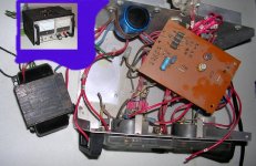
The starting point is an old power supply since it can yield me a transformer. The supply was made in 1986, and has a Hammond Filament 167 transformer inside. It will give me a centre tapped secondary of 25V rated at 4A (i.e. 100VA). So this will have to be a power-reduced stereo zen.
Heatsinks will be a challenge.
Is it safe to venture into the Pass Forum with Bipolar devices 😀
Well I have been captivated by the Zen papers, having read them recently I want to build one. I thought it would be in the spirit of the Zen simplicity to restrict myself to what I can find lying around (can it be done for $0?). And since I've only ever built a couple of ClassAB Bipolar amps I don't have any MOSFETs to play with.
The starting point is an old power supply since it can yield me a transformer. The supply was made in 1986, and has a Hammond Filament 167 transformer inside. It will give me a centre tapped secondary of 25V rated at 4A (i.e. 100VA). So this will have to be a power-reduced stereo zen.
Heatsinks will be a challenge.
Attachments
Member
Joined 2009
Paid Member
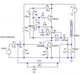
Here's the proposed schematic.
Power supply - assuming the Hammond will give me a full 25AC under load. Allowing for a capacitance multiplier I may get 30V if I'm lucky. Although the Trany is rated at 4A I'd better not ask for much more than half that which would be only 1A per channel. This seems too little - do you think I can get away with 1.5A per channel ? In my sims it's set up for 1.4A.
Current Source - I've had to change it a bit. The BJT is greedy for base current and this has to flow down through the bootstrap resistor chain. I've reduced the values of those resistors accordingly.
Output Device - that greedy base current means I need a Darlington pair (looks like Pavel's power follower eh?)
Input - the input impedance is a bit of a challenge. I looked at adding a single device buffer at the input but it adds more distortion and adds complexity. I'll probably drive this from the headphone output of a computer (is that bad ???) which will help. If I had a JFET in my toolbox....
Comments ?
Attachments
Hmmm, I would think a bipolar Zen would fly in the "coffin corner" like a spyplane... 10C hotter and she'll self destruct. 10C colder and it ain't in class-A no more 
Cheers!
Cheers!
Member
Joined 2009
Paid Member
The worry is the temperature sensitivity of BJTs and their tendency to keep on getting warmer ?
I was wondering about this. I thought that the upper power device would be held in check by the control transistor, Q4, which sits there monitoring the voltage drop across the resistor, R7 ?
The lower devices - are they not held in check by the fact that we have a CCS controlling the current that flows through them ?
I'm missing something obvious and stupid here aren't I.
The theory is sound, but cooked SS amps of similar design kept our TV shop going between hockey and football seasons 😉
Both MOSFET and BJT are susceptible to overheating, but BJT's moreso... forced air heatsinking methinks unless you have the $$$ for unmoveable chunks of metal 😀
Cheers!
Both MOSFET and BJT are susceptible to overheating, but BJT's moreso... forced air heatsinking methinks unless you have the $$$ for unmoveable chunks of metal 😀
Cheers!
Member
Joined 2009
Paid Member
forced air heatsinking methinks unless you have the $$$ for unmoveable chunks of metal 😀
I'm not opposed to small quiet fan, makes a heatsink waaaaaay more effective. The challenge is that I have to make this without buying stuff (this isn't going to work is it !) - but I do have a fan, a Midec, runs at 12V dc and sucks 170mA at full speed.
I do have some heatsink, it's extruded Al with lots of small fins, only 1 cm long fins. The fins run down the length of the heatsink which is about 8cm by 300cm. I can cut it up and make something of this perhaps.
- Status
- Not open for further replies.