INDEX
1. Background
2. Basic Design Goals
3. Drivers
4. Cabinets
5. Preliminary Crossover Design
6. Receiver
7. Testing Equipment
8. Construction
9. Crossover
10. The Sound(isn't that what it's all about?)
1. Background: Before Christmas I got the home audio bug and really wanted a new 5.1 system. My mediocre Sony system was over 10 years old by now and collecting dust in the garage. So I looked around online and a did a little research and was interested in the new Definitive Technology BP8000 series. I went and auditioned them a few times and really liked what I heard. DT was having a sale where you got the surrounds free if you bought the towers and center channel so I pulled the trigger and ordered the 8040's http://www.definitivetech.com/products/products.aspx?path=Floor-StandingSpeakers&productid=BP-8040ST from Crutchfield. I really did like them, but unfortunately I kept doing a little more general audio research and ended up catching the DIY bug. I really wanted to try my hand at building my own.
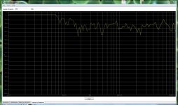
Measured response taken with AudioMes from my normal listening position of my BP8040's at -25dB with its subwoofer at mid level (take it with a grain of salt; read on):
I was also a little disillusioned at first thinking that I would save tons of money, but this was not the case. And the more I look around, the more I realize that this is generally the case with most builds. Yes you may come under budget of an equivalent commercial system would cost, or may get more bang for your buck. This is more true for the top end of the price point spectrum. Unfortunately most people, like myself are somewhere in the middle where savings are little to none, especially if you are a first timer like myself and had to buy most of the tools I needed.
Anyway, I found out that I could return my DT setup to Crutchfield no questions asked for a full refund minus $21 for three shipping labels and a $100 for freight for the towers. There are quite a few people who despise Crutchfield because their prices are high, etc. I found a couple places where I could have saved a few hundred bucks ordering online, but was very leery about it. Especially, since I couldn't find anywhere reputable that had the DT's I wanted under list price. Yet, with the surrounds being free, free shipping and no sales tax, I figured it was a descent deal. The bottom line is I think $121 was a very reasonable price to pay to audition this system for almost 2 months. I couldn't have done this if I bought them for $200 cheaper from some shyster on ebay. Therefore, I was very happy with my Crutchfield experience and recommend you don't totally write them off if you don't decides to go the DIY route. Hopefully I haven't angered the DIY audio gods too much.
2. Basic Design Goals
This was my first full build, not counting a sub I had just built, so I was forced to build something that was easy to moderately difficult. I wanted to duplicate the wide soundstage and off axis response of my bipolar Def Tech's 8040's. I also liked the "Super Tower" concept (even though DT kinda makes it sound like they are the ST pioneers, I doubt they were the first to do it)of saving space by putting a powered sub in the towers. Yet, I had just built a 12" TC Epic sub, so didn't need the extra low end punch in the towers. I also wanted to keep the D'Appolito driver layout. It seemed to work well in the DT's. Instead of doing a D'Appolito in front with a two way woofer/tweet in the back like the 8000 series DT's, I wanted to try using a D'Appolito in front and back like the 7000 series DT's. Finally, I also wanted to keep the slim and deep look of the DT's as much as possible. The less footprint the better.
This was my first full build, not counting a sub I had just built, so I was forced to build something that was easy to moderately difficult. I wanted to duplicate the wide soundstage and off axis response of my bipolar Def Tech's 8040's. I also liked the "Super Tower" concept (even though DT kinda makes it sound like they are the ST pioneers, I doubt they were the first to do it)of saving space by putting a powered sub in the towers. Yet, I had just built a 12" TC Epic sub, so didn't need the extra low end punch in the towers. I also wanted to keep the D'Appolito driver layout. It seemed to work well in the DT's. Instead of doing a D'Appolito in front with a two way woofer/tweet in the back like the 8000 series DT's, I wanted to try using a D'Appolito in front and back like the 7000 series DT's. Finally, I also wanted to keep the slim and deep look of the DT's as much as possible. The less footprint the better.
3. Drivers
I really wanted to use Scanspeak Revelator drivers, but they were way out of my price range with the woofers alone being $2K. I did a lot of researching online and would have liked to have completely copied someone else's proven build. But there are hardly any bipolar builds out there. So I ended up just looking for inspiration where I could find it. This ultimately lead me to the Troels and Zaph sites. I was really intrigued by Troels's Peerless HDS 830860 5.25" woofer/Vifa Tweet bookshelf speaker design. Peerless HDS PPB 830860 He claimed both drivers are good, especially for their price. Many others on the web confirmed this. I also looked at the smaller 4" 830870 Peerless woofer. The only way to keep the sleek DT look would be to use a smaller driver. Although, I didn't doubt that Troels was impressed by the relative bass of the 830860, I was a little skeptical and really doubted the 4" driver could come close to being able to play loud and accurate down to 80Hz so that it would integrate well with my sub. Yes, I had the manufactures SPL/freq graphs but take those with a grain of salt. So, I chose the 5.25" driver and mistakenly chose the Vifa XT25 Tweeter over the DX(more on this later).
I really wanted to use Scanspeak Revelator drivers, but they were way out of my price range with the woofers alone being $2K. I did a lot of researching online and would have liked to have completely copied someone else's proven build. But there are hardly any bipolar builds out there. So I ended up just looking for inspiration where I could find it. This ultimately lead me to the Troels and Zaph sites. I was really intrigued by Troels's Peerless HDS 830860 5.25" woofer/Vifa Tweet bookshelf speaker design. Peerless HDS PPB 830860 He claimed both drivers are good, especially for their price. Many others on the web confirmed this. I also looked at the smaller 4" 830870 Peerless woofer. The only way to keep the sleek DT look would be to use a smaller driver. Although, I didn't doubt that Troels was impressed by the relative bass of the 830860, I was a little skeptical and really doubted the 4" driver could come close to being able to play loud and accurate down to 80Hz so that it would integrate well with my sub. Yes, I had the manufactures SPL/freq graphs but take those with a grain of salt. So, I chose the 5.25" driver and mistakenly chose the Vifa XT25 Tweeter over the DX(more on this later).
Peerless HDS-P830860 http://www.madisound.com/pdf/spec_sheets/tympany_08172011/830860.pdf
Vifa XT25TG30-04 http://www.madisound.com/pdf/spec_sheets/tympany_08172011/XT25TG30-04.pdf
Vifa DX25TG09-04 http://www.madisound.com/pdf/spec_sheets/tympany_08172011/DX25TG09-04.pdf
Vifa XT25TG30-04 http://www.madisound.com/pdf/spec_sheets/tympany_08172011/XT25TG30-04.pdf
Vifa DX25TG09-04 http://www.madisound.com/pdf/spec_sheets/tympany_08172011/DX25TG09-04.pdf
4. Cabinets
I wanted to do something different than the plain rectangular "monkey coffin". Troels has several projects on his site (along with several on this site) that use beautiful cabinets to compliment the great sound of the drivers. Even though I am not a novice to woodworking, and ended up buying multiple tools for this project, these designs are way out of my league.
I ended up deciding to try and please my monkey and spice things up by angling the front and back walls up(adding extra depth to the bottom relative to the top)-thus, a trapezoid. Yet, this still seemed a little too plain so I ended up also angling the sides as well. After drawing the design sketches it looked as if this would add enough flare. Unfortunately this also doubled my build time.
Outside Dimensions:
top width: 9"
top depth: 12.5"
bottom width: 15"
bottom depth: 16.5"
height(without feet spikes installed): 35.25"
front top to bottom depth offset: 2.5"
back top to bottom depth offset: 1.5"
side top to bottom width offset: 3" on each side
top depth: 12.5"
bottom width: 15"
bottom depth: 16.5"
height(without feet spikes installed): 35.25"
front top to bottom depth offset: 2.5"
back top to bottom depth offset: 1.5"
side top to bottom width offset: 3" on each side
5. Preliminary Crossover Design
This area was what I was most concerned with. I am moderately knowledgeable in electronics but had never built a passive crossover before. I found "Passive Crossover Designer 7" (PCD7) Loudspeaker Design Software free online and started fooling around with it. Wow, there was a steep learning curve there. Not only did I have to learn the basics of crossover building, the PCD7 excel spreadsheet is VERY busy. Quite intimidating at first. Especially since at the time, I had limited internet access and couldn't find an in-depth tutorial and basically taught myself how to use it. I initially looked at the instruction sheet in the program, but hadn't done my homework yet to fully understand what was going on, so a painful hands on trial and error was the best way for me to learn. Later I found other resources that would have made things much easier in the beginning. The complexity of PCD7 is also one of its strengths if you can get comfortable enough to use it. From experience, it can be very cumbersome if you don' t know how to use it. For example, in some earlier preliminary designs, I manually entered all of the SPL and impedance data into the spreadsheet for the drivers by visually interpolating their SPL graphs because I could not find my driver's .frd and .zma files anywhere online to download. Not only is this not very accurate it is VERY, VERY tedious.
Luckily I stumbled upon "SPL Trace" SPL Tools. It's a convenient and free program that lets you import your own SPL/impedance vs frequency graphs as pictures. Then you can set the limits of the graphs, trace the curves, and create the .zma and .frd files for any driver that you have graphs for.
The PCD7 spreadsheet also has a box modeling tool. I didn't end up solely using it since I didn't see it in the spreadsheet until after I had found and used another modeling software: "WinISD Pro Alpha" LinearTeam.
I ended up using Troels's crossover as a starting point for mine. I wasn't sure if this was even a good place to start since I'm using two D'Appolito arrays instead of his single two way design. His has a second order parallel low pass filter for the woofer and a third order parallel high pass for the tweeter.
This is where I ran into problems with the PCD7 spreadsheet. I could use it to design a single D'Appolito array, but not two. But the more I thought about it, the more I wasn't sure if this was even relevant since the second array was facing to the rear and what you are hearing is what is being reflected off the walls slightly out of phase, delayed, etc. So I used the spreadsheet to design one D'Appolito array and figured I would just duplicate this design for the rear array to start with and maybe add some series resistance to the front drivers(-3 to 6dB) so that the fronts wouldn't drown out the rears. Not very scientific, I know, but then again I'm still learning.
6. Receiver
From my original purchase from Crutchfield I still had my Yamaha RX-V867 receiver RX-V867 - RX - AV Receivers - Audio & Visual - Products - Yamaha United States and am using it to drive my setup. Like most people have stated it has a relatively steep learning curve to fully use all of its features. Most of this has to do with several issues with the owner's manual. Despite it being 167 pages there are portions that don't fully explain how to use certain functions of the receiver. After 3 months of heavy use I still think there are a few things I haven't figured out. Despite this I am very happy with it. Parametric EQ, Pandora Radio, etc. Two thumbs up for a receiver under $500.
From my original purchase from Crutchfield I still had my Yamaha RX-V867 receiver RX-V867 - RX - AV Receivers - Audio & Visual - Products - Yamaha United States and am using it to drive my setup. Like most people have stated it has a relatively steep learning curve to fully use all of its features. Most of this has to do with several issues with the owner's manual. Despite it being 167 pages there are portions that don't fully explain how to use certain functions of the receiver. After 3 months of heavy use I still think there are a few things I haven't figured out. Despite this I am very happy with it. Parametric EQ, Pandora Radio, etc. Two thumbs up for a receiver under $500.
7. Testing Equipment
I looked online and found the free "AudioMeS" program. I also had a mic that came with my Yamaha receiver, used for automatic parametric eq calibration. These, along with an extra HDMI cable from my laptop to my receiver let me do some sound testing. I did a few tests of my DT's at listening position. What I wanted to do was throw away the manufacturer's SPL/freq response graphs and test the woofers/tweets individually in my cabinets after they were built, and use this data in PCD7. Unfortunately, I didn't do this because I began to doubt the accuracy of my test setup. After several tests, some of the graphs just didn't look right compared to what I was hearing and I doubted them for two main reasons:
I looked online and found the free "AudioMeS" program. I also had a mic that came with my Yamaha receiver, used for automatic parametric eq calibration. These, along with an extra HDMI cable from my laptop to my receiver let me do some sound testing. I did a few tests of my DT's at listening position. What I wanted to do was throw away the manufacturer's SPL/freq response graphs and test the woofers/tweets individually in my cabinets after they were built, and use this data in PCD7. Unfortunately, I didn't do this because I began to doubt the accuracy of my test setup. After several tests, some of the graphs just didn't look right compared to what I was hearing and I doubted them for two main reasons:
1. One main thing that I noticed was that the graph starts plotting at a certain SPL level(usually between -25 to -40dB). No matter how far the sound level of the speakers goes below that initial reference, it will only plot the response at or slightly below this reference. As the speakers sound level increases and goes above that initial reference level, then It seems to plot fairly accurately but for some reason, below that initial mark doesn't give accurate measurements.
2. Even though you can increase the total number of measurements taken across the 20-20K frequency range, there seemed to be gaps between some of the individual frequency measurements that showed up as exaggerated spikes or dips.
I'm not sure what I could have been doing wrong to attribute these problems to operator error. But if anyone has an idea, please let me know. Otherwise, I think AudioMeS is ok to give a general idea of what's going on, and definitely better than nothing. But still, I would like to see it up against a proven test setup to determine its accuracy.2. Even though you can increase the total number of measurements taken across the 20-20K frequency range, there seemed to be gaps between some of the individual frequency measurements that showed up as exaggerated spikes or dips.
8. Construction
Finally, to the heart of the discussion. I learned quite a bit from my subwoofer build. Mostly how not to do things. Case in point, for the sub baffles I used hole saws to drill out the airflow holes. I ended up with 30-40 holes in each baffle, some of which I ended up cutting out anyway to allow more air to pass through. This took countless hours that I could have saved if I would have cut most of the holes with a jig saw instead.
For the wood I used 3/4" and 1/2" MDF. I also used wood and drywall screws to fasten most pieces together. I don't see too many high end designs using screws as a primary fastener. I will wood putty over the recessed holes before I paint and finish them, so I have no issue with it. Wood glue was also used on all the joined pieces.
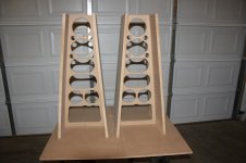
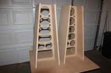
I started out by cutting out the main center baffle and the sides with 3/4" MDF. I did some guestimating of the final tweeter's vertical center height and then did a little trigonometry to figure out the appropriate angle for the front and back sides based off the horizontal listening distance from the tweeter to my ears(adding in the reflected distance off the back wall for the rear array). I came up with a 4 degree angle for the front and 2.5 degrees for the back. I also played around with the numbers for the side angles and came up with 5 degree angles for a +3" per side top to bottom width. The +3" on each side looked the best to me. Anything less and you lose the trapezoidal look. Why double the build time for something I would hardly notice? 5 degrees it was.
When I decided to add in the side angles I basically threw away my slim design goal because I couldn't have both. Not with a total +6" increase in top to bottom width-especially when using the 5.25" drivers. Plotting out the box response curve I needed ~2ft^3 to get the most out of a vented enclosure. This was about twice as big as I originally wanted. So I could have went with the 4" woofers and still maintain a little bit of the slimmer look, but I ultimately was more concerned with having descent low end midbass at the expense of the additional 3-4" increase in width. Now, I wish I had a 4" version to see/hear the difference because I think the smaller woofers would have surprised me just as much as the 5.25's did.
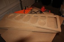
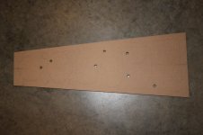
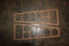
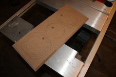
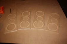
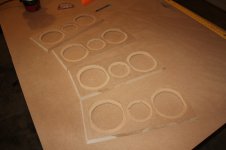
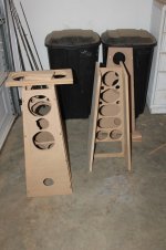
As you can see, I used a jig saw for almost all of the cutouts for the center baffle and routed out both sides of the cutouts. I probably should have made the cutouts a little bit smaller to increase the rigidity of the baffle. It wasn't flimsy by any means, but could have been a little more rigid. Support is the whole point of putting in the baffle. I was just so turned off by the hours and hours I spent drilling holes, that I went a little too far. All in all though, it worked out ok.
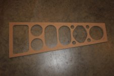
Next I cut out the front and back sides out of 1/2" MDF. I would have used 3/4" but I ran out, and couldn't see going out and buying another 4'X8' sheet for a couple of pieces. Plus, I didn't think I would really be compromising by using the 1/2".
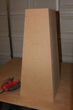
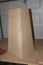
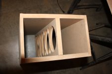
Finally, to the heart of the discussion. I learned quite a bit from my subwoofer build. Mostly how not to do things. Case in point, for the sub baffles I used hole saws to drill out the airflow holes. I ended up with 30-40 holes in each baffle, some of which I ended up cutting out anyway to allow more air to pass through. This took countless hours that I could have saved if I would have cut most of the holes with a jig saw instead.
For the wood I used 3/4" and 1/2" MDF. I also used wood and drywall screws to fasten most pieces together. I don't see too many high end designs using screws as a primary fastener. I will wood putty over the recessed holes before I paint and finish them, so I have no issue with it. Wood glue was also used on all the joined pieces.
I started out by cutting out the main center baffle and the sides with 3/4" MDF. I did some guestimating of the final tweeter's vertical center height and then did a little trigonometry to figure out the appropriate angle for the front and back sides based off the horizontal listening distance from the tweeter to my ears(adding in the reflected distance off the back wall for the rear array). I came up with a 4 degree angle for the front and 2.5 degrees for the back. I also played around with the numbers for the side angles and came up with 5 degree angles for a +3" per side top to bottom width. The +3" on each side looked the best to me. Anything less and you lose the trapezoidal look. Why double the build time for something I would hardly notice? 5 degrees it was.
When I decided to add in the side angles I basically threw away my slim design goal because I couldn't have both. Not with a total +6" increase in top to bottom width-especially when using the 5.25" drivers. Plotting out the box response curve I needed ~2ft^3 to get the most out of a vented enclosure. This was about twice as big as I originally wanted. So I could have went with the 4" woofers and still maintain a little bit of the slimmer look, but I ultimately was more concerned with having descent low end midbass at the expense of the additional 3-4" increase in width. Now, I wish I had a 4" version to see/hear the difference because I think the smaller woofers would have surprised me just as much as the 5.25's did.
As you can see, I used a jig saw for almost all of the cutouts for the center baffle and routed out both sides of the cutouts. I probably should have made the cutouts a little bit smaller to increase the rigidity of the baffle. It wasn't flimsy by any means, but could have been a little more rigid. Support is the whole point of putting in the baffle. I was just so turned off by the hours and hours I spent drilling holes, that I went a little too far. All in all though, it worked out ok.


Next I cut out the front and back sides out of 1/2" MDF. I would have used 3/4" but I ran out, and couldn't see going out and buying another 4'X8' sheet for a couple of pieces. Plus, I didn't think I would really be compromising by using the 1/2".


8. Construction (continued)
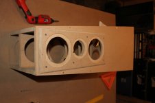
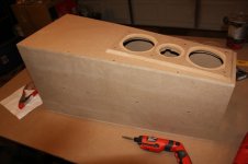
Next, to add a little bit more flare I decided to use a mounting plate/baffle to recess the drivers into. I also angle cut the edges at 60 degrees with my table saw. I drew the driver cutouts on the plate and decided to offset the tweeter a little bit left/right. I then routed out the driver recesses. After that, I positioned the baffles onto the cabinet and drew the cutouts on the cabinets. Once this was done, I cut these out and glued and screwed the baffles to the fronts and backs.
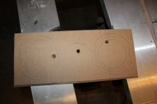

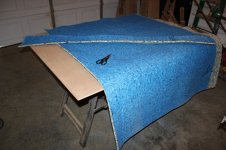
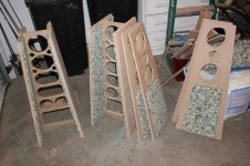
For cabinet damping I used indoor carpet padding and hot glued it to the inside walls. It was much cheaper than using some of the commercial products out there. I spent $12 for a 5'X8' piece from Lowes.
Next, to add a little bit more flare I decided to use a mounting plate/baffle to recess the drivers into. I also angle cut the edges at 60 degrees with my table saw. I drew the driver cutouts on the plate and decided to offset the tweeter a little bit left/right. I then routed out the driver recesses. After that, I positioned the baffles onto the cabinet and drew the cutouts on the cabinets. Once this was done, I cut these out and glued and screwed the baffles to the fronts and backs.


For cabinet damping I used indoor carpet padding and hot glued it to the inside walls. It was much cheaper than using some of the commercial products out there. I spent $12 for a 5'X8' piece from Lowes.


Construction (continued...again)
Another thing I was worried about was the absence of a solid baffle between the front and back woofers. I wasn't sure how the inside sound waves/pressure from each set of woofers would affect the opposing ones since they are directly behind each other and nothing between them. I decided to go with this layout anyway and use a polyfill stuffing to hopefully reduce the effects. Trying to cut down on cost some more I picked up some home insulation to use as a polyfill substitute and glued a small amount of this to both sides of the baffle. I'm not sure if I used enough. I think I will go back and add a little more later.

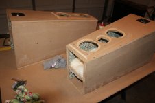
By now I had the cabinets mostly done except for the tops and bottoms. I had some scrap pieces of angle cut 1/2" MDF laying around and was using it to see how the angle cuts would look versus an unangled cut on top. Messing around I tried it on the sides also to see how it would look and it really looked nicer than the plain 90 degree edge. So I cut 1/2" side panels with a 45 degree edge angle to go on top of the 3/4" sides. This added another days worth of work, but I think it was worth it. My monkey appreciated this extra detail. Anyway, I had to cut these pieces freehand on the table saw because I couldn't use my table saw guide since the pieces were too big. By the end of the project I got pretty good at this, but it took the whole project to get there.
Next, I measured and angle cut the top plates at 60 degrees all around. For the bottom plates I continued the top to bottom angles of 3-5 degrees, angle cut and fastened them to the cabinets. I also cut four square bottom feet out of 3/4" MDF. These were angle cut at 30 degrees in opposite directions of the other angles. Then I installed the floor spikes in these. The feet also served another purpose. They lift the bottom of the cabinet off of the floor. This was necessary since I decided to cutout a space for the crossover on the bottom plate. I had to chose one side of the baffle to cut it out so I chose to install it on the front side of the baffle and not the rear. The crossover plate that I attached to the bottom, along with the bottom plate were routed, but the crossover plate still protruded out the bottom plate by ~1/8". I didn't want to route more than half the 1/2" thickness on both for fear that this would cause them to be too brittle. So I lessened the recess at the expense of the crossover plate sticking out. Not a problem since it can't be seen unless you get down to floor level and look. I also used 1/8"X1/2" gasket tape to ensure a good seal for the crossover plate. I screwed it into the bottom plate but do not plan on wood puttying the countersunk screw holes since I thought it essential that I be able to take this off if I needed to get to the crossover after painting and polyurethaning. Finally, I cut out the hole for the terminal block on the back and the 3" port on the front.
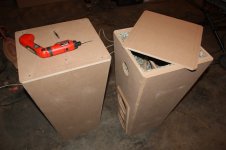
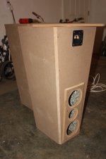
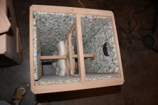
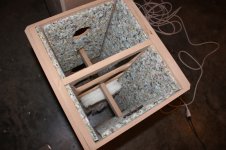
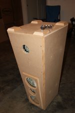
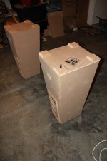
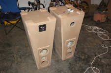
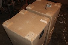
At this point I was pretty much done with the cabinets. I am going to paint and polyurethane them, but at a later date. The woodwork alone took me about 70hrs from start to finish and I still had to design and tweak the crossover.
Another thing I was worried about was the absence of a solid baffle between the front and back woofers. I wasn't sure how the inside sound waves/pressure from each set of woofers would affect the opposing ones since they are directly behind each other and nothing between them. I decided to go with this layout anyway and use a polyfill stuffing to hopefully reduce the effects. Trying to cut down on cost some more I picked up some home insulation to use as a polyfill substitute and glued a small amount of this to both sides of the baffle. I'm not sure if I used enough. I think I will go back and add a little more later.


By now I had the cabinets mostly done except for the tops and bottoms. I had some scrap pieces of angle cut 1/2" MDF laying around and was using it to see how the angle cuts would look versus an unangled cut on top. Messing around I tried it on the sides also to see how it would look and it really looked nicer than the plain 90 degree edge. So I cut 1/2" side panels with a 45 degree edge angle to go on top of the 3/4" sides. This added another days worth of work, but I think it was worth it. My monkey appreciated this extra detail. Anyway, I had to cut these pieces freehand on the table saw because I couldn't use my table saw guide since the pieces were too big. By the end of the project I got pretty good at this, but it took the whole project to get there.
Next, I measured and angle cut the top plates at 60 degrees all around. For the bottom plates I continued the top to bottom angles of 3-5 degrees, angle cut and fastened them to the cabinets. I also cut four square bottom feet out of 3/4" MDF. These were angle cut at 30 degrees in opposite directions of the other angles. Then I installed the floor spikes in these. The feet also served another purpose. They lift the bottom of the cabinet off of the floor. This was necessary since I decided to cutout a space for the crossover on the bottom plate. I had to chose one side of the baffle to cut it out so I chose to install it on the front side of the baffle and not the rear. The crossover plate that I attached to the bottom, along with the bottom plate were routed, but the crossover plate still protruded out the bottom plate by ~1/8". I didn't want to route more than half the 1/2" thickness on both for fear that this would cause them to be too brittle. So I lessened the recess at the expense of the crossover plate sticking out. Not a problem since it can't be seen unless you get down to floor level and look. I also used 1/8"X1/2" gasket tape to ensure a good seal for the crossover plate. I screwed it into the bottom plate but do not plan on wood puttying the countersunk screw holes since I thought it essential that I be able to take this off if I needed to get to the crossover after painting and polyurethaning. Finally, I cut out the hole for the terminal block on the back and the 3" port on the front.


At this point I was pretty much done with the cabinets. I am going to paint and polyurethane them, but at a later date. The woodwork alone took me about 70hrs from start to finish and I still had to design and tweak the crossover.
9. Crossover
After several hours learning and messing around with PCD7 I finally felt comfortable enough to use it. I basically started with Troels's design using a second and third order two way crossover. Using PCD7 my values for the components came up different from the start point. This is probably mainly due to using two woofers instead of one. After much tinkering I came up with a descent theoretical design that stayed within +/- 2dB.

Components:
So I ended up using one crossover for both MTM arrays with both tweeters in parallel and all four woofers in parallel on the same crossover. I was afraid that this might lower the impedance too low for my Yamaha receiver to handle, but the simulated impedance of one MTM array didn't go below 6 ohms. So I figured worst case scenerio I might get down to 3ohms(borderline?).
After a few days of tweaking I think I had thw sound where I wanted it.
Components:
Although they sounded good, I could tell that the DX tweeter sounded louder than the XT's. This was due to their sensitivity being higher than the XT's. So I knew I needed to make some tweaks to the crossover. For a quick short term fix I jumpered one of the 1.5ohm series resisters on the woofers lowering it down from 3 to 1.5ohms. This seemed to even out the tweeters with the woofers and seemed like a good point to put the towers on pause and enjoy the sound from what I had built so far.
After several hours learning and messing around with PCD7 I finally felt comfortable enough to use it. I basically started with Troels's design using a second and third order two way crossover. Using PCD7 my values for the components came up different from the start point. This is probably mainly due to using two woofers instead of one. After much tinkering I came up with a descent theoretical design that stayed within +/- 2dB.

Components:
woofer-
L2=0.7mH
C2=15uF
R3=1ohms
tweeter-
C9=4.7uF
C10=14.7uF
L9=0.3mH
I ordered several different sizes of caps, inductors and resistors to use for tweaking from Parts Express. Unfortunately, I didn't order enough to make two complete crossovers-one for each MTM array in a tower. This was a big oversight because as I started testing, and powered only one crossover/MTM array, it sounded like poo. The cabinet is not segregated between the two arrays. Only using half the drivers essentially created twice the desired cabinet volume. Also, the inactive woofers acted like passive radiators. The bottom line is that they didn't sound right.L2=0.7mH
C2=15uF
R3=1ohms
tweeter-
C9=4.7uF
C10=14.7uF
L9=0.3mH
So I ended up using one crossover for both MTM arrays with both tweeters in parallel and all four woofers in parallel on the same crossover. I was afraid that this might lower the impedance too low for my Yamaha receiver to handle, but the simulated impedance of one MTM array didn't go below 6 ohms. So I figured worst case scenerio I might get down to 3ohms(borderline?).
After a few days of tweaking I think I had thw sound where I wanted it.
Components:
woofer-
L2=0.7mH
C2=15uF
R3=3ohms(2-1.5ohm resisters in series)
tweeter-
C9=6.8uF
C10=10uF
L9=0.3mH
R2=1.0ohm
But then after looking around some more on the "interweb" I realized that I was using the wrong tweeter. I got the Vifa DX and XT tweeters confused and had ordered the XT instead of the DX. The DX has much better off axis response, which is one of the strengths of a bipolar system. When I ordered the XT's I didn't double check the manufacturer's data and assumed it was the one with the better off axis response. To make a long story short, I later ordered the DX and replaced the XT's. I noticed a big difference. I see why some prefer the DX and others the XT. If off axis response isn't a big deal for you then you might want to go with the XT. It sounded good even at high levels, but didn't go well with my design. Messing around with it I crossed it over down past 1KHz and it still held up nicely and sounded good(to my ears at least). After replacing it and listening to the difference it was a night and day between the two.L2=0.7mH
C2=15uF
R3=3ohms(2-1.5ohm resisters in series)
tweeter-
C9=6.8uF
C10=10uF
L9=0.3mH
R2=1.0ohm
Although they sounded good, I could tell that the DX tweeter sounded louder than the XT's. This was due to their sensitivity being higher than the XT's. So I knew I needed to make some tweaks to the crossover. For a quick short term fix I jumpered one of the 1.5ohm series resisters on the woofers lowering it down from 3 to 1.5ohms. This seemed to even out the tweeters with the woofers and seemed like a good point to put the towers on pause and enjoy the sound from what I had built so far.
10. The Sound(isn't that what it's all about?)
Since halfway finishing the pyramid crossovers, I have built my surrounds and center channel speakers. I'll post those builds in the future. After some well deserved time to relax and some research/studying I will try my hand at the crossover again to see how to improve it. I'm sure there are some passive crossover gurus that will look at my design and cringe. I know it's not perfect, but regardless, it sounds quite good to me.
Below is a pic of their measured response. I was only able to go as loud as -35dB on my receiver because the family was at home, and the test tones get very annoying/painful if I crank it up much more than this. Depending on what source I am listening to I usually listen between -25dB and lower. So I'll post a more strenuous measured response later when the family isn't around to suffer from the testing.
Response at -35dB measured from my normal listening position(~11' away):
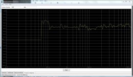
I really wanted to do an in-depth side by side comparison with my DT's, but I sent them back before I completed my towers. So this wasn't possible. Even though my pyramids sounded good in the sweet spot with the XT tweeter I was a little disappointed the first time I fired them up and listened off axis. They dropped off quick. As I stated earlier this was remedied when I replaced them with the DX's. One thing I thought was pretty neat with the DT's was that I could sit on my left side couch, with the speakers only toed in slightly and could still really hear the opposite(right) speaker quite clearly. The left speaker didn't drown it out like most setups would. It had to be close to 60 degrees off axis if not more. Mine are pretty close if not equaling this off axis response.
The sound staging is also quite good. I have them pulled out from my wall by about a foot, so I'm sure if I had the space and pulled them out even more they would probably sound better.
I must admit that Troels was not exaggerating when he complimented the 830860's low end response. With my current crossover setup they usually play too loud in the low end-something I would not have imagined. I think it has to do with the woofers fs being 62Hz which is causing a spike around this frequency. At this point I'm not sure how to realistically correct this with the crossover, so when the bass get's to be too much I have my parametric eq set to notch this out with a quick press on my receiver remote.
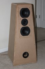
Even at an intermediate phase I think I've come close to meeting most of my goals. I really wanted to keep the footprint small and totally went in the opposite direction from this. The pyramids aren't massive, but they are much bigger than the 5.5"X11.5" footprint of the DTs. I really noticed this when I brought them into the living room.
As things progress I'll post updates. They look a little shabby in the pics since they are haven't been painted yet. But in person, I am very satisfied with their aesthetics. As I finished them and they took shape, I was surprised at how good they looked, even unfinished.
All horn tooting aside, I hope this post will help anyone thinking of doing a bipolar setup, and you learn from my many mistakes.
Bottom Line: two thumbs up from my monkey in the coffin (aren't opposable thumbs great?)
Since halfway finishing the pyramid crossovers, I have built my surrounds and center channel speakers. I'll post those builds in the future. After some well deserved time to relax and some research/studying I will try my hand at the crossover again to see how to improve it. I'm sure there are some passive crossover gurus that will look at my design and cringe. I know it's not perfect, but regardless, it sounds quite good to me.
Below is a pic of their measured response. I was only able to go as loud as -35dB on my receiver because the family was at home, and the test tones get very annoying/painful if I crank it up much more than this. Depending on what source I am listening to I usually listen between -25dB and lower. So I'll post a more strenuous measured response later when the family isn't around to suffer from the testing.
Response at -35dB measured from my normal listening position(~11' away):

I really wanted to do an in-depth side by side comparison with my DT's, but I sent them back before I completed my towers. So this wasn't possible. Even though my pyramids sounded good in the sweet spot with the XT tweeter I was a little disappointed the first time I fired them up and listened off axis. They dropped off quick. As I stated earlier this was remedied when I replaced them with the DX's. One thing I thought was pretty neat with the DT's was that I could sit on my left side couch, with the speakers only toed in slightly and could still really hear the opposite(right) speaker quite clearly. The left speaker didn't drown it out like most setups would. It had to be close to 60 degrees off axis if not more. Mine are pretty close if not equaling this off axis response.
The sound staging is also quite good. I have them pulled out from my wall by about a foot, so I'm sure if I had the space and pulled them out even more they would probably sound better.
I must admit that Troels was not exaggerating when he complimented the 830860's low end response. With my current crossover setup they usually play too loud in the low end-something I would not have imagined. I think it has to do with the woofers fs being 62Hz which is causing a spike around this frequency. At this point I'm not sure how to realistically correct this with the crossover, so when the bass get's to be too much I have my parametric eq set to notch this out with a quick press on my receiver remote.
Even at an intermediate phase I think I've come close to meeting most of my goals. I really wanted to keep the footprint small and totally went in the opposite direction from this. The pyramids aren't massive, but they are much bigger than the 5.5"X11.5" footprint of the DTs. I really noticed this when I brought them into the living room.
As things progress I'll post updates. They look a little shabby in the pics since they are haven't been painted yet. But in person, I am very satisfied with their aesthetics. As I finished them and they took shape, I was surprised at how good they looked, even unfinished.
All horn tooting aside, I hope this post will help anyone thinking of doing a bipolar setup, and you learn from my many mistakes.
Bottom Line: two thumbs up from my monkey in the coffin (aren't opposable thumbs great?)
An ambitious 1st project... will be interested in how it turns out.
dave
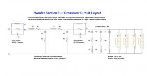
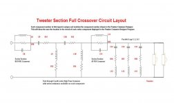
Yeah, at times I felt I bit off more than I could chew. The crossover is something I'm still going to work on. Any general suggestions are welcome. Below is the crossover layout. In a week or so I'll start over with the tweaking and see what happens.
woofer-
L2=0.7mH
C2=15uF
R3=1.5ohm
tweeter-
C9=6.8uF
C10=10uF
L9=0.3mH
R2=1.0ohm
And I still have to finish the cabinets. I painted my subwoofer black and put a couple coats of polyurethane over it. It turned out pretty good, but I would like to do a better job of both this time. Instead of using a brush I'll try the can sprays of each on some test pieces and see how that turns out.L2=0.7mH
C2=15uF
R3=1.5ohm
tweeter-
C9=6.8uF
C10=10uF
L9=0.3mH
R2=1.0ohm
Thanks for the response,
-mike
Last edited:
Crossover Typo
I see I had two typos in the crossover components:
I have no R3 resister
R4=1.5ohms
I have no no R2 resister
R13=1.0ohms
I would have changed this on the previous post, but I don't see how to edit the post a second time. Sorry.
I see I had two typos in the crossover components:
I have no R3 resister
R4=1.5ohms
I have no no R2 resister
R13=1.0ohms
I would have changed this on the previous post, but I don't see how to edit the post a second time. Sorry.
I don't see too many high end designs using screws as a primary fastener.
Largely because using screws -- particularily in MDF -- weakens the box vrs just using glue & clamps.
dave
For cabinet damping I used indoor carpet padding
From the pictures it look slike it is plastic based? It is not as effective as the cotton or wool stuff.
dave
Another thing I was worried about was the absence of a solid baffle between the front and back woofers...Trying to cut down on cost some more I picked up some home insulation to use as a polyfill substitute
Another holey brace tightly coupling the magnets of the drivers, coupling the 2 baffles & stiffening them (the baffle is the weakest panel in the speaker) goes a long way to maximizing the benefits of push-push nature of the bipole.
Fiberglass insulation is better than polyfluff, just not as nice to use. UltraTouch wall insulation is even better.
dave
Yeah, at times I felt I bit off more than I could chew. The crossover is something I'm still going to work on. Any general suggestions are welcome.
I'm not the guy to ask about XOs. I avoid them as much as possible. And if i use them, i keep them really low (100-400 Hz -- preferred) or really high (6k +) and am very careful in driver choice to keep the XOs simpe.
dave
Dave, thanks for the responses.
I only used the screws to hold the MDF together while the glue dried. I didn't have enough clamps and even if I did I don't know if could have gotten them to hold because of the odd cabinet shape. Hopefully the few screws I put in didn't compromise the rigidness too much if at all.
The carpet padding I'm using for damping has a thin rubberish film on the back of it. The rest of it is a cotton type material.
I know active crossovers are the way to go, but for now I have to go the passive route. I think I've gotten the crossover design figured out as best I can with my limited test equipment. I'll post the end product after I'm finished.
Yeah, I should have braced a little better. Live and learn.
Thanks again for your helpful insight
planet10 said:Largely because using screws -- particularily in MDF -- weakens the box vrs just using glue & clamps.
I only used the screws to hold the MDF together while the glue dried. I didn't have enough clamps and even if I did I don't know if could have gotten them to hold because of the odd cabinet shape. Hopefully the few screws I put in didn't compromise the rigidness too much if at all.
planet10 said:From the pictures it look slike it is plastic based? It is not as effective as the cotton or wool stuff.
The carpet padding I'm using for damping has a thin rubberish film on the back of it. The rest of it is a cotton type material.
planet10 said:I'm not the guy to ask about XOs. I avoid them as much as possible. And if i use them, i keep them really low (100-400 Hz -- preferred) or really high (6k +) and am very careful in driver choice to keep the XOs simpe.
I know active crossovers are the way to go, but for now I have to go the passive route. I think I've gotten the crossover design figured out as best I can with my limited test equipment. I'll post the end product after I'm finished.
planet10 said:Another holey brace tightly coupling the magnets of the drivers, coupling the 2 baffles & stiffening them (the baffle is the weakest panel in the speaker) goes a long way to maximizing the benefits of push-push nature of the bipole.
Yeah, I should have braced a little better. Live and learn.
Thanks again for your helpful insight
- Status
- Not open for further replies.
- Home
- Loudspeakers
- Multi-Way
- Bipolar Trapezoidal Pyramid Build