Hi all!! I found a 0-50v, 1A power supply circuit in a RCA SOLID STATE DEVICES MANUAL SC16, pages 680-681. Has anyone here had experience with this circuit. It uses CA3086 as a zener reference and a CA3130 as an error amplifier. Someone said that the RCA line was taken over by Harris Intersil??? I know this is old but I haven't seen anything that will go to + and - 80v. If I wanted bi-polar positive and negative tracking voltages to 80 v, then I was thinking about using mj15003 and mj15004 as the pass transistors. But what is the advantage of having bipolar bjt's versus just building two identical power supplies. It must be tracking ability between the two. I would appreciate any advice and or pointing me toward a an article that is more up to date than 1980. I've looked but they are always Lm337 and LM317 and that's not gona cut it to 80v. Thanks Ray
They make high voltage regulator ICs. For example, this one goes to 125v, and the 700ma current rating can be increased with pass traqnsistors.
http://www.ti.com/lit/ds/symlink/tl783.pdf
http://www.ti.com/lit/ds/symlink/tl783.pdf
Tracking is nice to have.
But I think adjustable current limiting is far more important and useful.
But I think adjustable current limiting is far more important and useful.
Thanks, Enzo and Andrew. Yes, the RCA circuit has current limiting adjustment and yes I would like that very much. I would like to know what is the advantage of a mirror imaged bi-polar PS where the - side is pnp and the positive side is npn versus building two identical PS say with both npn pass transistors and connecting them where the bottom one puts out negative voltage. My HP power supply does this and is not mirror imaged.
if you do build a dual channel PSU then you MUST build them so that they are isolated.
That isolation requirement removes the option to combine a pair of opposite polarity supplies.
You need two supplies from separate windings and through separate rectifiers.
This arrangement allows you to series connect the supplies if you need so and also allows parallel connection if extra current capability is needed.
The isolation also allows one supply to power a circuit and the other supply to fit into some elevated voltage tapping in the circuit. That could not be done if there were a common ground between the dual supplies.
For amp testing I use a couple of bipolar supplies -- the easiest is one with a variac controlling the primary of a big toroid transformer with separate rectifiers and caps.
You can use depletion MOSFET's as an "easy to implement" current limiter. Walt Jung has some discussion in his article "Current Sources 101" on the waltjung.org website.
You can use depletion MOSFET's as an "easy to implement" current limiter. Walt Jung has some discussion in his article "Current Sources 101" on the waltjung.org website.
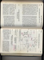
RCA power supply in solid state manual
OK, I looked at the Jung article and I didn't see much of anything above 18v. I'm sure there are more up to date solutions than this one but I live far from an engineering library. I looked at the Linear Technology at the LT1083 but again nothing that would go to 80 volts. I will build two identical power supplies and connect them where the bottom serves - 80v. But how do I get them to track obviously with some type of opamp circuit. I will use mj15003-4 and the modern mj transistor cor the 2n2102. But I really unsure as to the reliability of the cmos or dmos harris opamp and transistor array.
OK, I looked at the Jung article and I didn't see much of anything above 18v. I'm sure there are more up to date solutions than this one but I live far from an engineering library. I looked at the Linear Technology at the LT1083 but again nothing that would go to 80 volts. I will build two identical power supplies and connect them where the bottom serves - 80v. But how do I get them to track obviously with some type of opamp circuit. I will use mj15003-4 and the modern mj transistor cor the 2n2102. But I really unsure as to the reliability of the cmos or dmos harris opamp and transistor array.
Attachments
A major problem of wide range, high voltage/current linear regulated supplies is that unless you use them near their max. voltage, the dissipation and construction cost become enormous. This is why you see so few high voltage linear supplies and those that are about, usually only offer low current.
Jackinnj's suggestion to use a variac or multi-tapped transformer is adequate and much simpler, whilst it could still track voltage reasonably and can easily include the all important current limiting, since amps seldom need voltage regulation but do need this for amp. testing and setup.
Randy Slone published a good, basic and relatively inexpensive adjustable limiting dual supply design. It's on p389 of his "High Power Amplifier Construction Manual" (Mc Graw-Hill) with recommendations for use. This is an older title but easily read and cheap from Amazon etc.
IMO, tracking is nice if you get it for free, but completely unnecessary. I run twin Kepco supplies on my bench and the ability to run constant current is a huge feature I use constantly (no pun intended). You don't just want current limiting for protection, but also the ability to run at an adjustable constant current setting.
Just for fun, download some Kepco, Lambda, HP and similar supply manuals and study the schematics.
Just for fun, download some Kepco, Lambda, HP and similar supply manuals and study the schematics.
Spike trash in the noise floor
It is time to re-cap my Leach Low TIM and the Leach Super Amp I built around 1979 and I want to upgrade the power supplies. My system is tri and bi amped and I have 6 LTIM and two Super Leach for subwoofers. They never reach clipping because my speaks are very efficient. Is anyone using chokes to clean up those spike charging currents or has anyone addressed that in 100 watt+ solid state power amplifiers. What is the cleanest rectifier, a HEXFRED? The ones in there are just heavy silicon bridges. Any advice appreciated. Ray
It is time to re-cap my Leach Low TIM and the Leach Super Amp I built around 1979 and I want to upgrade the power supplies. My system is tri and bi amped and I have 6 LTIM and two Super Leach for subwoofers. They never reach clipping because my speaks are very efficient. Is anyone using chokes to clean up those spike charging currents or has anyone addressed that in 100 watt+ solid state power amplifiers. What is the cleanest rectifier, a HEXFRED? The ones in there are just heavy silicon bridges. Any advice appreciated. Ray
Check your rectifier to see if there are any spikes on the secondary output.
If it is spike free, then leave the rectifiers alone.
Check to see how rounded the sawtooth voltage is at the output of the smoothing bank. If it is well rounded, then leave it alone.
Only if there is spikiness or sharp looking waveform after the smoothing caps do you need to look at attenuating the HF garbage that gets past the transformer or generated by the rectifiers.
Stop worrying about it.
More likely to give improvement is a proper search through and critical examination of the wiring methods used to interconnect all the modules inside the amplifiers. DON'T strip it all out. LOOK carefully and see if any single wire pair could be improved. LOOK carefully at how the Grounding has been implemented.
A member here designed and developed a bench supply, with excellent results. It avoids opamps which takes care of the voltage range problem.
http://www.diyaudio.com/forums/power-supplies/177212-lab-power-supply-design-build.html
Another way is to look at what the Mastech supplies do - they use seperate windings to create a +12/-12 supply for the opamps, which is then floated on the main output. Quite a neat trick, but means either two transformers per channel, or a custom wound transformer. The transformer for the control supplies only needs to be low power though, so a small 100mA transformer is enough.
Secondary ouutput?"Stop worring about it!
Check your rectifier to see if there are any spikes on the secondary output.
Thanks Andrew! There is a .1 uf MKP across the secondary of each power transformer at the input of the bridge. I'm wondering if "snubbing" each diode with a .01 uf ceramic and a 470K resistor in parallel with each diode will clean up any more trash on a + and - 50v high current power amp supply. I've read some posts where this works for preamps. The trash is always there on each amp albeit low down on the noise floor. But it would seem that that would be amplified along with the program material. Each mono channel has it's own power transformer, there are six supplies. I also have read where more modern amps are regulating the power to the input voltage gain stages and allowing the current gain stages to be connected directly to the large 10,000, 75v filter caps reservoir.
The "snubbing resistor" should be value selected to damp any tendency to oscillate when transients pass. This usually means a lowish value of resistor. 470k is probably 100,000 times too big. (yes 5 decades).
The cap is there to stop the DC blowing up the damping resistor.
The cap does not damp the resonances !
The cap is there to stop the DC blowing up the damping resistor.
The cap does not damp the resonances !
- Status
- Not open for further replies.
- Home
- Amplifiers
- Solid State
- Bipolar bench power supply for testing audio circuits