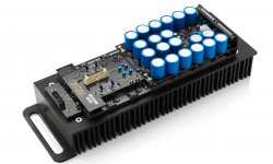
Okay, I found this DIY amp on internet, and it looks kind of interesting with Darlington coupling on each output transistor, so my question is, has anybody build this thing and how does it behave?
Link to site.
Big amplifier-general
Link to site.
Big amplifier-general
Attachments

Generally this is basic Hitachi-Otala topology with especially point is individual drivers for each output transistor. This thing may help to avoid using high current, high voltage transistors for driver duty what worst than small devices (Cob, Hfe, Ft...).
It seems Mark Levinson has used this idea in their amps, the ML No#536. Each driver for each output trans.
It seems Mark Levinson has used this idea in their amps, the ML No#536. Each driver for each output trans.
Attachments
MJE15032/33 were $4 each 5 years ago. They are ~$1.50 now. Use one driver and a big heat sink on it.Generally this is basic Hitachi-Otala topology with especially point is individual drivers for each output transistor. This thing may help to avoid using high current, high voltage transistors for driver duty what worst than small devices (Cob, Hfe, Ft...).
It seems Mark Levinson has used this idea in their amps, the ML No#536. Each driver for each output trans.
A serious drawback is the Darlington layout of all driver and power devices wich slows down the power stage unnecessarily. Either, and as yet suggested, replace those video MJE's by one modern device per side, and/or replace both 470R resistors in one branch by a single 1k between both emitters/bases.
Best regards!
Best regards!
Why does this slowing down happen?...which slows down the power stage unnecessarily...
The VAS must be capable driving more base currents into the darlingtons, but that's in milliamps, whereas a single driver for more end-bjt's must drive into amps instead. The VAS runs on some 15mA @ 50Vps.
I didn't check the complete schematic, but the bias pot hanging in the air makes me think that the schematic probably has other errors, so check the schematic carefully before attempting to build it. There are better, proven designs out there.
Last edited:
It's not hanging, but an awful way to draw a circuit. It is in series properly and the wiper is curled backwards crossing a leg....the bias pot hanging in the air...
It's not hanging, but an awful way to draw a circuit. It is in series properly and the wiper is curled backwards crossing a leg.
The pot will do nothing as shown, To me the schematic looks like a quick first draft that has not been reviewed yet.
If you want an amplifier with parallel darlington transistors at the output - here you will find the AB 100:AB100 Class AB Power Amplifier
As the driver pulls down the other side, base current can flow through the single resistor directly to that driver instead of the output bus, which first would have to get down.Why does this slowing down happen?
The VAS must be capable driving more base currents into the darlingtons, but that's in milliamps, whereas a single driver for more end-bjt's must drive into amps instead. The VAS runs on some 15mA @ 50Vps.
Best regards!
Which driver, which other side, which base current, which single resistor.As the driver pulls down the other side, base current can flow through the single resistor directly to that driver instead of the output bus, which first would have to get down.
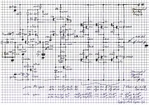
Let's name the bjt's:
- first stage diff pair left-right Q1-Q2, cascodes ditto Q3-Q4, CS Q5
- second stage diffs l-r Q11-Q12, cascode of q11 is Q13, right side of CM is Q14, bias is Q15
- end group I npn-top Q21-Q23, pnp-down Q22-Q24
- group II Q31-Q33 & Q32-Q34; group III Q41-Q43 & Q42-Q44
- emitterresistors according to their Q#
Please elaborate!
Thank you guys for inputs.
I see the bias pot is hanging in schematic, but in pcb layout I can see its connection.
Slow amplifier? Maybe, well I build "slow amps" before with very good sound, I checked my drawers and I have majority of parts, best way to find out is to build the darn thing, if it with ease can drive Martin logan cls it must be powerfull, we'll see.
I made a quick but very rough more traditional drawing by hand last night, sorry for the annoying gridlines. The scanner did odd things and not solved yet.
The pot is not hanging. I doubt the original specs, and a lot is depending on the capacity of the supply.
The pot is not hanging. I doubt the original specs, and a lot is depending on the capacity of the supply.
Attachments
- Home
- Amplifiers
- Solid State
- Big solid amplifier. Anybody build this?