Jawen, is there a coil in serie with the woofers inside the cab ? What is the load : BR, sealed ? Looks like a band pass, very strange...
What you can try is to remove a woofer from the cab and measure it on the soil in front of your home if you have wire long enough and a laptop for the soundcard with the mic on the floor as well.
What you can try is to remove a woofer from the cab and measure it on the soil in front of your home if you have wire long enough and a laptop for the soundcard with the mic on the floor as well.
Jawen, is there a coil in serie with the woofers inside the cab ? What is the load : BR, sealed ? Looks like a band pass, very strange...
What you can try is to remove a woofer from the cab and measure it on the soil in front of your home if you have wire long enough and a laptop for the soundcard with the mic on the floor as well.
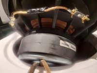
Yes its so strange!
The Peerlees 830847 XXLS have 2 x 8 ohm´s coils, so its in serie at the coil to 16 ohm and paralell utside with 2 x "the same" XXLS
Its a vented 102 liter netto tuned to 22 hz.
I used bitumen-cement when i mount then, so its going to be hell to get it loose.
Attachments
Just so you know, i use 2 Krell F.B.I amp for this MTM and woofer.
One for the woofers, and one for the MTM.
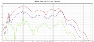
Last mesaurement on Left woofer was from MTM amp side, the earlier mesaurement was from the wooffer amp.
Seems strange if one of the krell F.B.I have no hz over 150 hz ?
One for the woofers, and one for the MTM.
Last mesaurement on Left woofer was from MTM amp side, the earlier mesaurement was from the wooffer amp.
Seems strange if one of the krell F.B.I have no hz over 150 hz ?
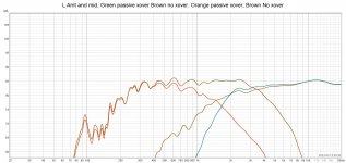
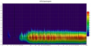
I'm not a filter specialist, very far from it; but it seems to me you have your answer with the measurement from above at seeing the green curve : your big dip is a measurement difraction issue, so the woofers are making bass as the blue and red curves are showing.
Most of the time for diyers, the bass and a part of the low mid must be simulated because it is impossible to measure rigth without anechoic environment.
The most acurate way is like you made : very near the woofer dust cap and also sumed at the output of the port if Bass reflex or band-pass design. cab side on the floor with mic on the floor. A mid measurement above 600/700 hz circa works if the mid is at iso distance of the floor and ceilling : in your case around 1.25 meter (and of course furnitures apart from this short area), so with a gating measurement of something 6 to 7 ms if my memory serves me well. Some dips in the 100 hz to 200 hz and also around 300 hz are often due to the room interaction.
If I wrote a wrong information here, specialists will correct. Your woofer seems to be fine
Edit : as a diy enthusiast the thread at diyaudio called Open Source Monkey Coffin (OSMC) loudspeaker by the op Mbrenwa describes well the process of measurement and simulation, with try & errors and design process evolution : a good how to, very inspiring.
🙂

I'm not a filter specialist, very far from it; but it seems to me you have your answer with the measurement from above at seeing the green curve : your big dip is a measurement difraction issue, so the woofers are making bass as the blue and red curves are showing.
Most of the time for diyers, the bass and a part of the low mid must be simulated because it is impossible to measure rigth without anechoic environment.
The most acurate way is like you made : very near the woofer dust cap and also sumed at the output of the port if Bass reflex or band-pass design. cab side on the floor with mic on the floor. A mid measurement above 600/700 hz circa works if the mid is at iso distance of the floor and ceilling : in your case around 1.25 meter (and of course furnitures apart from this short area), so with a gating measurement of something 6 to 7 ms if my memory serves me well. Some dips in the 100 hz to 200 hz and also around 300 hz are often due to the room interaction.
If I wrote a wrong information here, specialists will correct. Your woofer seems to be fine
Edit : as a diy enthusiast the thread at diyaudio called Open Source Monkey Coffin (OSMC) loudspeaker by the op Mbrenwa describes well the process of measurement and simulation, with try & errors and design process evolution : a good how to, very inspiring.
Thanks for your words and hope other people comes around with their thoughts.
I'm completely exhausted today....You have piles of cables for everything in 15 centimeters of space behind the stereo bench, which weighs a lot because many components are in it. Reconnect solder & run extra wires from everything & measure, measure, measure.
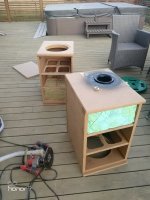
So now the xovers are outside "the box" and no working speakers, and it´s not going to be fun solder the xover ( because I have such short cables)
And have also disconnected everything & moved around heavy amp and preamps, so at least a couple of hours to get everything back.
But its real interesting everything about sound, and also how sound works.
Had put the real mesaurements in XSIM, and are working with getting a better 340-1K curve...And also lower the xover-point for the AMT a little.
Regards John
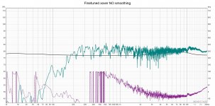
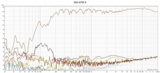
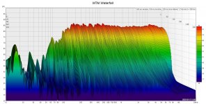
Have done some finetuning and masaurements in passive xover, but dont have enough experience to know "where to stop" and be satisfied.
Mesaurement and phase and distortion and waterfall.
For yoy guy´s, how does this look ?
Happy if i get some comments and suggestions.
Also not good to set different settings in REW, and maby "go deeper" in mesaurements.
Best regards John
Mesaurement and phase and distortion and waterfall.
For yoy guy´s, how does this look ?
Happy if i get some comments and suggestions.
Also not good to set different settings in REW, and maby "go deeper" in mesaurements.
Best regards John
Attachments
Quite interesting that XSIM and actual mesaurements in the room are so near eachother!
Even if i have spend much time.
Think i end up with having 2 order filter for the AMT insteed of 3 order, and finetuned with cap-change on mid and a resistor on both mid and high.


Regards John/Sweden
Even if i have spend much time.
Think i end up with having 2 order filter for the AMT insteed of 3 order, and finetuned with cap-change on mid and a resistor on both mid and high.
Regards John/Sweden
It would be helpful if you could describe the measurement process you are using. What microphone are you using? What is the measurement software/hardware? Are you applying a time gating or windowing ? How much distance between the driver and the nearest large surface (wall/floor/ceiling), and how much distance between the mic and the nearest large surface?
j.
j.
It would be helpful if you could describe the measurement process you are using. What microphone are you using? What is the measurement software/hardware? Are you applying a time gating or windowing ? How much distance between the driver and the nearest large surface (wall/floor/ceiling), and how much distance between the mic and the nearest large surface?
j.
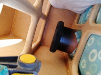
Sorry J I didn't think of that in all the "fixing" and thinking.
Im using a calibrated UMIK and the software REW.
And im not familier with the setting in REW, so i think its "standard", but took a dump on the side so you can se.
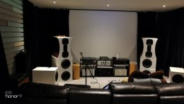
The speaker is about 55 cm out from the front wall, with toe-in.
Center MTM is about 1,1 meter from floor and 1,4 meter to the ceiling
Center of AMT 1,1 meter from left wall, 1,1 M from floor and 1,4 M from ceiling
The mic is 1,1M from floor , 1,4 M from the ceiling and 1,52 M from left wall.
Is a bit of chaos now while I work and measure, but here is a pic att the room/mic/speaker
Attachments

Double channels soundcards measurements is the way to go for measurement for better acuracy. But as you already made the cabinetw it will not help you, I mean the design is almost made as the cabinet is there. Anyway, double channel measurement is more acurate when it comes to work on timing, phase for the filter. I bthibk you will find a lot of litterature about that here.
Anyway, what is working not too bad is a magnitude curve than loose 5 dB to 10 dB between the low end and the high end. You already know it will be difficult to measure in your room for the loww end but you can try to simulate it and maybe the knoledgeable guys here (I am not) will help about how to catch "something in the low end to try to EQ a little if you use DSP (plate amps, etc) for the bass.
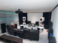
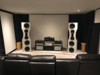
Just from experience for a better soundstage and less boomy signature I will respect a 1 metr to 1.5 meter between the front baaffle and the wall behind. seems ok about the side walls with the size limitation you have plus the screen. It is often better to choose a little asymetric distance between the speaker and the side wall between both channel. You can start from 20% of non symetry and works from there by try & error if your hear differences.
The 2.5 m heigth is a little not enough but as it seems to me a dedicated Home-Cinema, you can try a diffusor on the ceilling in front of the projector if it doesn't hide projection of course.
Very hard to setup, at least from my limited experience, there is though a dedicated section here at DIYAUDIO about room layout 🙂
Not a lot said, but hopes that helps a little.
Anyway, what is working not too bad is a magnitude curve than loose 5 dB to 10 dB between the low end and the high end. You already know it will be difficult to measure in your room for the loww end but you can try to simulate it and maybe the knoledgeable guys here (I am not) will help about how to catch "something in the low end to try to EQ a little if you use DSP (plate amps, etc) for the bass.
Just from experience for a better soundstage and less boomy signature I will respect a 1 metr to 1.5 meter between the front baaffle and the wall behind. seems ok about the side walls with the size limitation you have plus the screen. It is often better to choose a little asymetric distance between the speaker and the side wall between both channel. You can start from 20% of non symetry and works from there by try & error if your hear differences.
The 2.5 m heigth is a little not enough but as it seems to me a dedicated Home-Cinema, you can try a diffusor on the ceilling in front of the projector if it doesn't hide projection of course.
Very hard to setup, at least from my limited experience, there is though a dedicated section here at DIYAUDIO about room layout 🙂
Not a lot said, but hopes that helps a little.
Just from experience for a better soundstage and less boomy signature I will respect a 1 metr to 1.5 meter between the front baaffle and the wall behind.
Hi and thanks diyiggy
I have about 55-60 cm behind speaker, and speaker is quite deep so baffle is around 1,3 M.
It is often better to choose a little asymetric distance between the speaker and the side wall between both channel. You can start from 20% of non symetry and works from there by try & error if your hear differences.
The left wall is sound treated, so its 15 cm air/stone wool/air, behind the "visible" wall with colored planks and fabrics.
Think the left and right speakers differance to the wall is around 35-40 cm.
My bass is so dry and not a tendency to be boomy.
you can try a diffusor on the ceilling in front of the projector if it doesn't hide projection of course.
Yea, i have thought about it a bit before, but havent done anything yet.
Recomendations on what pattern on the diffuser ?...Im a newbi at that.
measurement is more acurate when it comes to work on timing,
I often read treads about DIY and sometimes they talk about "timing" and delay.
Do you know how to measurements that, and REW maby can do that ?
difficult to measure in your room for the loww end but you can try to simulate it
How do you simulate that?
Some program or ?
Best regards John
no particular experience with REW, but starting his measurement journey with a true individualed calibrated mic (from 100 euros to...) needing a 48V power supply is the way from the soundcard with a standalone adc/dac from it for true time delay measurement is a must.
I am not a specialist, but here as you design is almost finished, maybe you should use multi aera measurements positions and try an assymetric passive filter to setup the delay in the passband of the filter cut - off seen from around listening area.
You need to know the exact impedance of the filters at their cut-off frequency, hence impedance measurement in their cab, raw of the filter first.
Hope the experienced guys here about measurements help you, they know way more than me, jut hope I started the ball for members to come 🙂
From what I can tell, it seems that you are using the "as-measured" responses of your drivers, right down to the lowest frequencies. This technique may not provide you with enough accuracy at low frequencies.
To get the most accurate low frequency measurement, you will need to make far field gated measurements and merge them with near field measurements. Far field measurements capture the higher frequencies (above 500 Hz approximately), and near field captures the low frequencies).
The far field measurements are made at a distance of 0.5 m to 1.0 m, and a time window (or time gate) of 4 - 8 ms is applied. The measuring distance is dependent on the width of the speaker, and a good rule of thumb for a tall speaker is to measure at a distance of 3x the width. The time window is dependent on the distance to nearest large surface. Usually this is the floor. The time window is chosen to capture the direct sound of the driver, but to exclude the first reflection. If the driver is 1300 mm above the floor, the time window would be about 5 ms.
The near field measurement is made with the mic almost touching the cone. For this measurement you do not use a time window, or you set the window for a very long interval such as 200 ms.
The next step is to merge the far field measurement and the near field measurement. VituixCad is the tool I use to do this, but there are others. The attached document explains how and why this is done.
Once you have a "merged" frequency response of each driver, you will have much more information to help you understand what is going on with your measurements and your simulations.
Attachments
- Home
- Loudspeakers
- Multi-Way
- Big dip between active and passive filter around crossingpoint?