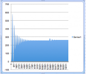
PSUD simulation snapshot. I may not be reading it right, but it seems to show that L1 sees a max of 350mA ? Could be a problem - I think it's rated for 200mA.
I don't think I trust this simulation - it's showing 1.7kV max at L1
I couldn't find the diodes under discussion in PSUD so I just put in something with a high voltage rating.
I don't think I trust this simulation - it's showing 1.7kV max at L1
I couldn't find the diodes under discussion in PSUD so I just put in something with a high voltage rating.
Attachments

Last edited:
Look at the plots. It may be that the PSU has subsonic ringing, or that it assumes too low a value for stray capacitance of the first choke. Does 5k load get you above the critical current?
Look at the plots. It may be that the PSU has subsonic ringing, or that it assumes too low a value for stray capacitance of the first choke. Does 5k load get you above the critical current?
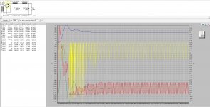
I use a “home grown” algorithm for these calculations. There's definitely ringing going on from the storage of the LC tank circuits and the high peak charging current on L1 during startup. About 11 Hz. Subsonic!
The homegrown 100 μs per step approximation yields similar results to PSUD, with a somewhat higher over-voltage, but the same post-ringing stable voltage. Beware LCLC circuit ringing!
There's an implication that all changes in load would have an equal “ringing while adapting” response. Not sure how large, but it could be. I'll see if I can do a time-domain modelling of this.
GoatGuy
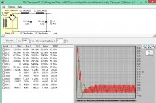
OK getting the hang of PSUD.
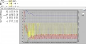
A load of 8K gives me the expected load of around 34mA, above the critical load for the first choke.
C plot shows me the voltage across the 2 caps - doesn't exceed 500 (I have 2 x 350V caps in series with a voltage dividor / bleeder to give me a 700V rating.
IL is the current through the chokes. Concerned that L1 sees an initial peak of 350mA ish (rated for 200mA) while L2 sees 260mA rated for 80mA). Less than a quarter of a second - should I be concerned about this ?
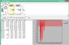
VBR shows the voltage over the Bridge Rectifier - which goes to -1500 !
GoatGuy - how did you do that time domain analysis ?
EDIT
Adding in a 1nF cap before the first choke brings the peak voltage across the BR down to -650V, but doesn't change the initial current surge through the chokes.
A load of 8K gives me the expected load of around 34mA, above the critical load for the first choke.
C plot shows me the voltage across the 2 caps - doesn't exceed 500 (I have 2 x 350V caps in series with a voltage dividor / bleeder to give me a 700V rating.
IL is the current through the chokes. Concerned that L1 sees an initial peak of 350mA ish (rated for 200mA) while L2 sees 260mA rated for 80mA). Less than a quarter of a second - should I be concerned about this ?
VBR shows the voltage over the Bridge Rectifier - which goes to -1500 !
GoatGuy - how did you do that time domain analysis ?
EDIT
Adding in a 1nF cap before the first choke brings the peak voltage across the BR down to -650V, but doesn't change the initial current surge through the chokes.
Attachments

Last edited:
Looking again the transformer needs to be specified in Vrms. Mine is the Audio Note Trans-0103 with secondaries of 400-300-0-300-400. I'm using the 300 CT, so Vrms will be 212 (300 / 1.414).
Please correct me if I have this wrong.
Changing the TX to 212 Vrms shows the V across the TX swinging between +300 and -300, so I think it's right. The bad news is that it's totally trashed the voltage I was expecting at B+. Looking for 250ish, but now settles around 180.
Are the secondaries on mains TX specified as pk-pk or RMS ?
Switching to using the 400-0-400V secondaries gives me around 240VDC on B+. Still have the inrush current which is back within choke ratings by 0.1 seconds after startup. Is it worth thinking about a thermistor to limit inrush current ?
Last edited:
Secondaries are usually specified in RMS voltage.
Subsonic ringing of LC smoothing sections is fairly common. Using lower quality chokes with higher resistance can help. Or add subsonic 'snubbers'.
Subsonic ringing of LC smoothing sections is fairly common. Using lower quality chokes with higher resistance can help. Or add subsonic 'snubbers'.
A snubber is a cap and resistor in series. The idea is that at sufficiently high frequencies the cap connects the resistor to the circuit and this damps a resonance. Connect across one of the smoothing caps.
As a first stab, try using a resistance of around sqrt(L/C) (so sqrt(10H/18uF) = 745) and a capacitor similar to the smoothing caps. So maybe 1K and 10uF. I don't think PSUD2 can do this, so you will need to use Spice.
As a first stab, try using a resistance of around sqrt(L/C) (so sqrt(10H/18uF) = 745) and a capacitor similar to the smoothing caps. So maybe 1K and 10uF. I don't think PSUD2 can do this, so you will need to use Spice.
A snubber is a cap and resistor in series. The idea is that at sufficiently high frequencies the cap connects the resistor to the circuit and this damps a resonance. Connect across one of the smoothing caps.
As a first stab, try using a resistance of around sqrt(L/C) (so sqrt(10H/18uF) = 745) and a capacitor similar to the smoothing caps. So maybe 1K and 10uF. I don't think PSUD2 can do this, so you will need to use Spice.
ok thanks. I'm struggling to get LTSpice to do what I want, mainly because I don't have the data it needs to model the AN mains TX. I'll persevere.
There are 4 simple ways to lower the Q factor of a LC circuit in the power supply.
1. Increase C or lower L, affecting the resonant frequency as well.
2. Increase idle current draw.
3. Increase series resistance to the choke through PT, rectifier or the choke itself.
4. Add series resistance to C - I do not recommend this for audio. 😀
1. Increase C or lower L, affecting the resonant frequency as well.
2. Increase idle current draw.
3. Increase series resistance to the choke through PT, rectifier or the choke itself.
4. Add series resistance to C - I do not recommend this for audio. 😀
By combining a choke and capacitor, you make a system between two passive elements that can store energy. One does it with a magnetic field, the other with a electric field. When two elements like this are connected together and exchange energy, they have a system resonant frequency and a Q factor.
Example of a resonant system - a pendulum swinging left and right - there is an exchange between potential energy and kinetic energy.
A high Q will be when there is little friction on the pendulum from the bearings and from the air. This means very little losses and the pendulum will take a long time to stop swinging at it resonant frequency after being excited.
A low Q will be if the pendulum system is inserted will water. The later will "damp" the oscillation of the pendulum and it will stop swinging much sooner. The losses are higher.
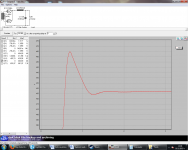
The same happens in an LC circuit. A high Q will give a high-amplitude, slow decaying transient at the resonant frequency - it is undesirable.
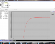
A very low Q however will make the circuit reacting slowly to changes. Too much of it is undesirable too.
You can simulate these things at PSUD2.
Edit: I attached examples of high Q and low Q LC by altering the Rdc of the choke. Notice the difference between the transients. Simulated with PSUD2.
Example of a resonant system - a pendulum swinging left and right - there is an exchange between potential energy and kinetic energy.
A high Q will be when there is little friction on the pendulum from the bearings and from the air. This means very little losses and the pendulum will take a long time to stop swinging at it resonant frequency after being excited.
A low Q will be if the pendulum system is inserted will water. The later will "damp" the oscillation of the pendulum and it will stop swinging much sooner. The losses are higher.
The same happens in an LC circuit. A high Q will give a high-amplitude, slow decaying transient at the resonant frequency - it is undesirable.
A very low Q however will make the circuit reacting slowly to changes. Too much of it is undesirable too.
You can simulate these things at PSUD2.
Edit: I attached examples of high Q and low Q LC by altering the Rdc of the choke. Notice the difference between the transients. Simulated with PSUD2.
Attachments
Last edited:
For UF4007 : Avg I is 1.0A. Surge is 30A, C is 17pF
For UF5408 : 3A, 150A, 36pF
MUR8100E : 16A, 100A, 30pF
Need to use same yardstick, such as 4V reverse across junction. First 2 diodes use that yardstick, but MUR8100E doesn't have that spec, unless the characteristic curve is looked at - then it is approx 240pF.
By combining a choke and capacitor, you make a system between two passive elements that can store energy. One does it with a magnetic field, the other with a electric field. When two elements like this are connected together and exchange energy, they have a system resonant frequency and a Q factor.
Example of a resonant system - a pendulum swinging left and right - there is an exchange between potential energy and kinetic energy.
A high Q will be when there is little friction on the pendulum from the bearings and from the air. This means very little losses and the pendulum will take a long time to stop swinging at it resonant frequency after being excited.
A low Q will be if the pendulum system is inserted will water. The later will "damp" the oscillation of the pendulum and it will stop swinging much sooner. The losses are higher.
The same happens in an LC circuit. A high Q will give a high-amplitude, slow decaying transient at the resonant frequency - it is undesirable.
A very low Q however will make the circuit reacting slowly to changes. Too much of it is undesirable too.
You can simulate these things at PSUD2.
Edit: I attached examples of high Q and low Q LC by altering the Rdc of the choke. Notice the difference between the transients. Simulated with PSUD2.
Got it - thanks for the clarity
Need to use same yardstick, such as 4V reverse across junction. First 2 diodes use that yardstick, but MUR8100E doesn't have that spec, unless the characteristic curve is looked at - then it is approx 240pF.
OK thanKS
Attached PSU with and without that first 1nF cap
I just LTSpiced your circuit. There will be an under-damped resonance through the PT secondary and the conducting diode(s) due to PT winding leakage inductance. I didn't use a 1N4007 diode - I'll try and get that model.
A full-bridge winding is worse (than a full-wave CT winding) with regard to the abrupt change in PT winding current at diode commutation - the total winding current flips from one polarity to the other.
An RC snubber across the PT winding is definitely worthwhile including by the looks of the simulations. The Quasimodo technique on this forum is a great way to assess the snubber values for your circuit.
Tim you're a star! Would you mind sending the model to me? Not to avoid the work, but so I can see what you did.
So you'd put the snubber on the transformer primary?
So you'd put the snubber on the transformer primary?
Thanks for the model Tim. Couple of questions if I may.
I had been trying to model the mains transformer as a primary winding in series with a 240AC 50Hz source coupled with 2 secondary windings for the centre-tap. I was really struggling at that point as LTSpice needs me to know things I don't know about the TX. Instead you simplified it as a voltage source in series with an inductor with very low inductance and low series resistance. Much easier. Is that a common trick ? So effectively we only have the mains tx secondary in circuit. But not centre-tapped ?
Voltage source : I'm in UK so I changed the voltage source to 50Hz. I notice you put the amplitude to 398V - can I ask why ? You have ended up with a smoothed DC voltage of around 241V. I'm confused about how transformer voltages are specified and how simulations need to see them. My mains tx has options for;
300 - 0 - 300
400 - 0 - 400
Will those be RMS or peak-peak ?
PSUD needs the TX specified in RMS - LTSpice specifies amplitude, does it mean peak-peak ? I don't know what is specified as what and what needs converting from/to RMS ?
I've been working on using the 300-0-300 and looking to get 255V ish. I may need to rethink.
Last edited:
- Status
- Not open for further replies.
- Home
- Amplifiers
- Power Supplies
- Big choke Little choke