I'm building a power supply for my new balanced phono stage, choke filtered LCLC. Transformer into bridge rectifier, B- & B+ taken from here so each is Half-Wave-Recitified.
I have 10H and 20H chokes - currently planning to put the 10H first, followed by 18uF cap, then 20H, then 18uF. Bleeders across both caps (voltage dividors, as the 18uF is actually 2 x 36uF in series to give plenty of voltage headroom).
What's the criteria for deciding whether to put the 10H first or the 20H ? The 10H are AudioNote 165 (10H, 200mA, 80DCR), 20H are AudioNote 180 (20H, 50mA, 240DCR).
Operating current will be around 34mA, the voltage after the bridge rectifier should be around 290V, so above critical for even the 10H.
Last edited:
I'm building a power supply for my new balanced phono stage, choke filtered LCLC. Transformer into bridge rectifier, B- & B+ taken from here so each is Half-Wave-Recitified.
Can you link to a schematic, as your description of half wave rectified doesn't seem right.
Have you simulated the design using PSUD2 - that would indicate the peak choke current level. The second choke sees a lower peak current, so is preferably your lower current speced choke (20H).
You are obviously aiming at low output ripple level. Were you contemplating tuning the first choke for maximum 2nd harmonic ripple reduction?
How are you managing rectifier dI/dt and dV/dt noise - valve diodes - smallish filter cap before first choke?
Ciao, Tim
Appreciate the response Tim thanks. Attached image is several versions out of date - I'll convert my visio to an image later and repost. It's quite possible I've described it wrongly but I hope not as that might mean I've also misunderstood it. This is my first real build, although I've modded my own amps and preamps before. Pretty much learning as I go, with the guidance of a friend and help from this forum.
I did download LTSpice but not yet familiar enough with it to try and simulate this. Your comment about the second choke seeing the lower peak current - THANKS that's exactly what I was looking for confirmation on. I'll put the 10H first, 20H second.
Tuning the first choke for 2nd harmonic ripple reduction - This article is what I read before with interest... http://www.qsl.net/i0jx/supply.html ... It's an RF article but the principles make sense.
I plan to look at that but as a newbie I think I've taken on all I can for now. After a couple months of reading, understanding, analysing, drawing and calculating my head will explode if I try and cram any more in just yet. I figure on getting this design built and working, listen to it and measure it. I'd love to then be able to add that tuning and hear the difference. Perhaps I should do it now, but hey I have to leave myself some improvement steps right ? 🙂
As for your comment on managing rectifier noise - ok you completely lost me sorry. Perhaps the schematic will clarify ?
Attachments

Last edited:
Placing the lowest impedance filter first (with the 10H) will result in a (marginally) lower ripple.What's the criteria for deciding whether to put the 10H first or the 20H ?
A sim with PSUD or LTspice could tell you by how much

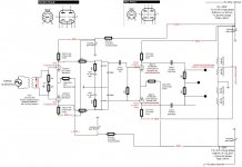
Your PSU circuit still shows a full-wave rectifier yet calls it a half-wave rectifier.
You haven't shown any 0V connection between the secondary CT and the first set of caps. The 0V seems to fly past the rest of the PSU! Getting grounding right in a PSU is as important as getting component values right.
Why use such small caps and big chokes? That was the way things were done in the 1950s, because bigger caps were not available then at reasonable prices and size.
As a comment, I would still refer to the transformer and the filter as seeing full-wave rectification waveforms.
PSUD2 from Duncan Tools is very informative and well worth the effort - you can use it for all those supplies to get a better understanding - much simpler learning curve than LTSpice.
Yes, choke tuning isn't needed upfront, and can be a learning path if you are keen later on.
PSUD2 will give you some indication of how the rectifier can generate large dV/dt and dI/dt waveforms - they need to be managed, otherwise they can easily egress to your amplifier circuitry. Softening the step waveforms and controlling where currents loop are well worth aiming for. Valve diodes are very soft switches. Nowadays you can use ss diodes such as UF4007 that have negligible reverse recovery effect, and very low off-state capacitance, to avoid some noise issues. Adding a low value cap between diodes and choke can alleviate step behaviour, and provide some protection for the choke to voltage transient stress. PT leakage inductance may also be a concern.
Thanks all - shows how much I still need to get.
The PSU diagram could be clearer - the caps for B+ and B- ground to it (obviously with B- I'd need to ensure I connected the positive node if I was using electrolytics).
Clearly I need to better understand FWR vs HWR. Back to the reading.
I'll have a go at the PSU software thanks.
I'm not using valve rectifiers, using SS. I'll post the part numbers when I get home.
No I don't need the current rating. Guess this is an example where over engineering doesn't pay.
I don't understand what's meant by off state capacitance - will Google.
I don't understand what's meant by off state capacitance - will Google.
No I don't need the current rating. Guess this is an example where over engineering doesn't pay.
I don't understand what's meant by off state capacitance - will Google.
Hmmm ok, I understand the words but not sure why it would be bad to overdo that.
Put it another way - what criteria should be used to select either a bridge rectifier or individual diodes for this design ?
The way I see it is that when the diodes are off, then they should preferably disconnect the PT secondary winding from the DC supply and amp circuitry.
SS diodes with negligible reverse recovery aim to minimise current flow directly after diode current reaches zero.
SS diodes with minimal off-state (reverse biased) capacitance aim to minimise current flow during the entire period the diode is effectively off. That parasitic capacitance allows dV/dt related current to pass - where the voltage on the PT side of the diode is not just a high amplitude sine at mains frequency, but also includes all the mains harmonics (especially those that contribute to 'flat-top'), and mains related noise that gets past the PT, and in addition also the transient dV/dt glitch when diode current reaches zero and PT winding leakage inductance causes the diode terminal voltage to 'step'.
Hence I suggest using a diode with sufficient, but not excessive current rating, and if you are really keen then use two in series for each 'diode'.
Last edited:
Use PSUD2 to determine what the operating, and initial turn-on peak current levels are likely to be. A very common diode used is UF4007 - check its operating and single surge current specs. The next diode in common use with larger current rating is UF5408. You will notice the capacitance increases with current rating of those devices, and that they have the same nominal reverse recovery time spec.
Did you have any reason to choose D-MUR8100E ?
Did you have any reason to choose D-MUR8100E ?
Keep in mind that many comments here are about parasitic effects - which in the light of day may achieve no tangible or measurable improvement - sort of like amps with twisted pair heater wiring when other amps have very open heater layouts and the user hears no adverse affect - or all those amps using 1N4007 rather than UF4007 diodes.
Similarly, DF96's query about why you are using chokes, which many would find to be a cumbersome and expensive path to take.
But this is diy - so you really only have to answer to yourself, and enjoy the path taken.
Similarly, DF96's query about why you are using chokes, which many would find to be a cumbersome and expensive path to take.
But this is diy - so you really only have to answer to yourself, and enjoy the path taken.
Thanks. Running these questions past more experienced people helps improve my understanding - I'm still very much a newbie. We've cleared up my mistake about HWR for one, and I would never have considered off state capacitance of diodes.
The amp I'm building has already been built and sounds superb to my ears. My brother wants his back and the friend who built it gives me guidance where he can but I need to learn.
I like the sound of choke driven amps. My hifi journey took me to modding my preamp several years ago quite heavily. It was an Audio Note M3 and I changed it from cap filtered to choke filtered - I recall that being one of those oh wow moments.
I really appreciate the time people take to help others like me learn - thanks.
Hi,
Many years ago I found this little article very helpful in showing how to simulate different power supplies with the same chokes and caps in PSUD, and the process to optimize the PS output
https://www.dhtrob.com/overige/pdf/dhtrob_psu.pdf
Cheers, Erik
Many years ago I found this little article very helpful in showing how to simulate different power supplies with the same chokes and caps in PSUD, and the process to optimize the PS output
https://www.dhtrob.com/overige/pdf/dhtrob_psu.pdf
Cheers, Erik
Hi,
Many years ago I found this little article very helpful in showing how to simulate different power supplies with the same chokes and caps in PSUD, and the process to optimize the PS output
https://www.dhtrob.com/overige/pdf/dhtrob_psu.pdf
Cheers, Erik
Thanks Erik. Excellent surname.
- Status
- Not open for further replies.
- Home
- Amplifiers
- Power Supplies
- Big choke Little choke